
Installation Guide

NX-1700E Card Reader
11
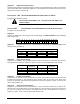
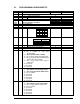
LOCATION 242 PROGRAMMING THE OPTIONS AND READER PARTITION
(4 segments of binary data)
Segment 1 System Options:
LED1 - "On" if reader is enabled for User Card Programming.
LED2 - "On" if optical tamper is enabled. (Default is “On”)
LED3 - "On" if reader buzzer is to follow typical keypad buzzing.
LED4 - "On" if ding-dong chime enabled (dependent on option 3 and chime being enabled).
LED5 - “On” if relay driver function is to be logged as Code Entry.
LED6 - Reserved.
LED7 - Reserved.
LED8 - Reserved.
Segment 2 LED1 (Green) Options:
LED1 - "On" to follow Ready status of system. (Default is “On”)
LED2 - "On" to toggle with the Relay Driver activation. (Default is “On”)
LED3 - "On" if inverted.
LED4 - Reserved.
LED5 - Reserved.
LED6 - Reserved.
LED7 - Reserved.
LED8 - Reserved.
Segment 3 LED2 (Red) Options:
LED1 - "On" to follow Armed status of system. (Default is “On”)
LED2 - "On" to toggle with the Relay Driver activation.
LED3 - "On" if inverted.
LED4 - Reserved.
LED5 - Reserved.
LED6 - Reserved.
LED7 - Reserved.
LED8 - Reserved.
Segment 4 Reader Partition:
LED1 - "On" if reader is in Partition 1. (Default is “On”)
LED2 - "On" if reader is in Partition 2. (Default is “On”)
LED3 - "On" if reader is in Partition 3. (Default is “On”)
LED4 - "On" if reader is in Partition 4. (Default is “On”)
LED5 - "On" if reader is in Partition 5. (Default is “On”)
LED6 - "On" if reader is in Partition 6. (Default is “On”)
LED7 - "On" if reader is in Partition 7. (Default is “On”)
LED8 - "On" if reader is in Partition 8. (Default is “On”)
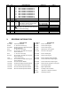
LOCATION 243 PROGRAMMING THE DOOR PROP ZONE
(1 segment of numerical data)
Enter the zone number that will be monitored for sounding the Door Prop Alarm. Program a 0 (default) to
disable this function. See Location 244, Segment 3 for the length of time the zone is monitored before
sounding the alarm. This location must be programmed with a valid zone in order for a Door Control
Module, if installed, to work properly. (Default is 0)