TruVision Megapixel IP Dome Camera Quick Start Guide P/N 1070297-EN • REV A • ISS 09NOV10
Copyright © 2010 UTC Fire & Security. All rights reserved. Trademarks and The TruVision name and logo are trademarks of patents UTC Fire & Security. GE and the GE monogram are trademarks of the General Electric Company and are under license to UTC Fire & Security, 9 Farm Springs Road, Farmington, CT 06034-4065, USA Contact For contact information, see information www.utcfireandsecurity.com.
Content Introduction 4 Package contents 4 Installation environment 4 Cable requirements 5 Camera dimensions 5 Setting up the camera 6 Connecting the devices 7 Vandal-proof megapixel IP dome camera connections 9 Mounting the dome cameras to a wall or ceiling 9 Accessing the camera over the internet 10 Overview of the Web browser window 11 Network and streaming configuration 12 Configuring the camera 14 1.3 megapixel camera main menu 15 2.
Introduction This pocket guide provides basic information on setting up and using the TruVision megapixel cameras. 1.3 megapixel IP dome cameras: TVD-M1120-3-N 1.3 megapixel vandal-proof dome TVD-M1120-3-P 1.3 megapixel vandal-proof dome 2.0 megapixel IP dome cameras: TVD-M2110-2-N 2.0 megapixel dome TVD-M2110-2-P 2.0 megapixel dome TVD-M2110V-3-N 2.0 megapixel vandal-proof dome TVD-M2110V-3-P 2.
Cable requirements Cable type Requirements Data For RS-485: 22 gauge (0.64 mm) shielded, twoconductor, twisted-pair (STP) cable Video 75 ohm coaxial cable with BNC ends Power 24 VAC cable Camera dimensions Figure 1: Megapixel IP dome camera 1.
Setting up the camera Note: If the light source where the camera is installed experiences rapid, wide variations in lighting, the camera may not operate as intended. For detailed instructions, please refer to the user manual. To quickly put the camera into operation: 1. Prepare the mounting surface. 2. Set the DIP switches to the desired positions and connect the power cable, alarm I/O cables, RS-485 cable, audio cables and network cable to the camera. 3.
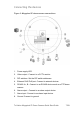
Connecting the devices Figure 3: Megapixel IP dome camera connections 1. Power supply LED. 2. Video output.. Connect to a CCTV monitor 3. DIP switches. Set the DIP switch addresses 4. Ethernet RJ45 PoE port. Connect to network devices. 5. RS-485 A+, B-. Connect to an RS-485 device such as a PTZ dome camera. 6. Alarm output . Connect to an alarm output device. 7. Alarm input. Connect to an alarm input device. 8. Ground. Connect to ground.
9. Audio output. Connect to an audio output.. 10. Audio input. Connect to an audio input. 11. Power supply. Connect +12 VDC or +24 VAC power supply. Setting the DIP switch addresses Switches 6 to 10 are not used at this time, so it does not matter whether they are set to on or off.
Vandal-proof megapixel IP dome camera connections Figure 4: Vandal-proof megapixel IP dome camera connections 1. Ethernet RJ45 PoE connector. Connect to the network devices. 2. Power supply cord. Connect +12 VDC or +24 VAC power supply. 3. Audio input jack. Connect to an audio input. 4. Audio output jack. Connect to an audio output. 5. Alarm I/O cable. Connect alarm input (IN, G) and output 6. RS-485 A+, B-. Connect to an RS-485 device such as a PTZ dome camera.
Accessing the camera over the internet The camera Web browser lets you view, record, and play back recorded videos as well as manage the camera from any PC with Internet access. To access the camera online: 1. In the Web browser enter the camera’s IP address. Use the tool, IP Finder, enclosed on the CD to find the IP address of the camera (default is 192.0.0.64). The Login dialog box appears. 7. Enter your user name and password. User name: admin Password: 1234 Click OK.
Overview of the Web browser window Figure 5: Web browser interface 1. Menu toolbar. Lets you do the following: Log on and log off the system. This can only be done in live mode. View live video. Play back video. Search for event logs. There are four main information types: All, Alarm, Notification and Operation. Configure settings. Note: The Playback and Log functions can only be used when an SDHC card is inserted in the camera. 2. Viewer. View live or playback video.
3. PTZ controls. Lets you control a PTZ camera when connected using RS-485 port. Also used to access main menu via “Preset 95” to configure the camera. 4. Video image settings. Adjust video image settings such as brightness, contrast, saturation, and hue. 5. Audio setting. Turn bi-directional audio on or off. 6. Video function. Lets you do the following: Record live video. Take a snapshot of the video. Start live view. 7. Camera. View video and record video from this camera.
Figure 6: Example of a configuration screen - Device parameters Note: The On-screen display (OSD) menus are in English only. Table 2: Overview of the configuration parameters Configuration folder Description Device information Defines the device name and number as well as enables the overwrite and video scaler options. Channel parameters Defines the OSD properties of camera information, recording schedule, recording settings for alarm events, alarm response, and overlay text.
Configuration folder Description Alarm parameters Defines how the camera handles alarms such as input type, notification of alarms, and response schedules and duration. Notification parameters Defines the methods to be used to alert for internal errors in the system. User management Defines who can use the camera, their passwords and access privileges. HDD configuration Defines how to format the SDD card used in the camera. Upgrade remotely Defines how to upgrade the camera’s firmware.
1.3 megapixel dome camera main menu 2.
Specifications Operating temperature -10 to +60 ℃(14 to 140 °F) Power supply 24 VAC ±10% / 12VDC ±10%, PoE (Power over Ethernet) Power consumption 4 W max. (10 W max. with ICR working) Dimensions 1.3 megapixel IP dome camera: 68 × 63 × 158 mm (2.71 x 2.48 x 6.25 inches) 2.0 megapixel IP dome camera: 160 × 134 mm (6.30 x 5.27 inches) Weight EN 16 600 g (1.