MODELS H2OI60D H2O60E H2O60DE H2OI80D H2OI80E H2OI80DE H2OI115D H2OI115E H2OI115DE H2O INDIRECT-FIRED WATER HEATERS WITH DUAL COIL SOLAR HOT WATER STORAGE TANK APPLICATIONS DUAL COIL INDIRECT FIRED WATER HEATERS WITH OR WITHOUT ELECTRIC BACKUP INDIRECT FIRED WATER HEATERS SINGLE COIL WITH ELECTRIC BACKUP INSTALLATION, OPERATION & MAINTENANCE MANUAL 60, 80, 115 Gallon D = Dual Coil E = Electric Backup Element Conforms to UL STD 174 Certified to CAN/CSA STD C22.2 No.
Table of Contents I. General Information & Safety Instructions................................................................................. 2 Dimensions and Capacities................................................................................................... 4 II. Pre-installation Considerations................................................................................................. 6 III. Piping.........................................................................................
Heat transfer medium must be water or other non-toxic fluid having a toxicity rating or class of 1, as listed in clinical Toxicology of Commercial Products, latest edition. The pressure of the heat transfer medium must be limited to a maximum of 60 psig by a listed safety or relief valve. DO NOT store or use gasoline or other flammable vapors or liquids in the vicinity of this or any other appliance.
Table 1 - Dimensions and Capacities Model Storage Volume Top Coil Heating Surface Bottom Coil Heating Surface Gals. Sq. Ft. Sq. Ft. Ht. Pipe Connections Max. Working Pressure Approx. shipping Wt. Dia. NPT (psi) Lbs. Dimensions (Inches) Single Coil - No Electric Backup H2OI115 115 - 8.9 74.0 28.0 1" NPT 150 175 H2OI80 80 -- 8.0 56.0 28.0 1" NPT 150 140 H2OI60 60 8.3 62.0 23.5 1" NPT 150 125 Single Coil - with 3500 watt Electric Backup H2O115E 115 - 8.9 74.0 28.
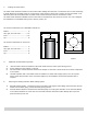
DUAL COIL UNITS ELECTRIC BACKUP UNITS T+P VALVE TOP COIL SUPPLY TOP COIL RETURN COLD WATER IN HOT WATER OUT BOTTOM SOLAR COIL SUPPLY BOTTOM SOLAR COIL RETURN 1.5 DUAL COIL UNITS TOP COIL 3/8" ID THERMAL WELL 4" X 10" ELECTRICAL BOX 1/2" NPT RECIRC. RETURN PORT TOP HEATING COIL FOR BACKUP 3/8" ID THERMAL WELL BOTTOM COIL 3/8" ID THERMAL WELL DRAIN VALVE BOTTOM HEATING COIL FOR SOLAR TYPICAL ALL ELECTRIC BACKUP UNITS Heat exchanger coil outputs Model Max. Recovery (gal/hr.
II. Pre-installation Considerations Inspect shipment carefully for signs of damage. All equipment is carefully inspected and packed. ECR’s responsibility ceases upon delivery of the water heater to the carrier in good condition. Any claims for damage or shortage, must be filed immediately against the carrier by the consignee. No claims for variances or shortages will be allowed by the Manufacturer, unless they are presented within sixty days after receipt of the equipment.
1. Circulator Sizing. Refer to Table 2 for the minimum flow through the water heater coil and the pressure drop at minimum flow. Calculate the pressure drop across all piping and fittings connected to the water heater zone. Be sure to include all zone valves, check valves, and shut-off valves. It is recommended that the water heater zone be piped with 1” pipe around the entire loop on typical residential sites. A.
C. Locating the water heater. The water heater should be located in an area where water leakage from the tank or connections will not result in damage to areas adjacent to the water heater or to lower floors of the structure. When such a location can not be avoided, a suitable drain pan must be installed under the water heater, and the drain pan must be connected to a drain. The water heater should be installed as close to the boiler as is practical for easy access for service.
F. Water Quality Improper water quality will reduce the expected life of the water heater. Hard water, sediment, high or low Ph, and high levels of chlorides in the domestic water should be avoided. Sediment and hard water will eventually coat the heating coil inside the water heater and reduce the rate of hot water production and may, eventually cause a failure. High or low Ph and/or high chloride concentrations will cause corrosion and eventually failure.
B. Water boiler piping. See Figures 2 and 3. 1. 2. Determine where the boiler, the space heating, and the water heater connections should be made based on the type of piping system that is either in place, or is to be installed for a new hydronic system installation. See Figure 2, Boiler Water Piping with Zone Circulators, and Figure 3, Boiler Water Piping with Zone Valves. It is recommended that 1” pipe and 1” zone valves be used on the water heater zone.
Figure 1 Domestic Water Piping Pipe Relief Valve Discharge to within 6" of floor, see Section III Notes.
Pipe Relief Valve Discharge to within 6" of floor, see Section III Notes. Figure 3 - Boiler water piping with zone circulators Pipe Relief Valve Discharge to within 6" of floor, see Section III Notes.
Pipe Relief Valve Discharge to within 6" of floor, see Section III Notes. Figure 5 Figure 6 Pipe Relief Valve Discharge to within 6" of floor, see Section III Notes.
SOLAR PIPING Hot Water Can Scald! Water heated to temperature for clothes washing, dish washing and other sanitizing needs can scald and cause permanent injury. Pipe Relief Valve Discharge to within 6" of floor, see Section III Notes. Figure 8 Hot Water Recirculation Hot Water Recirculation for Solar Hot Water Storage Tanks Hot water recirculation is for the continuous circulation of hot water for instant hot water at the hot water faucets.
IV. Electrical 1. 2. 3. Install electric wiring and grounding in accordance with the National Electrical code and local regulations. All water heaters are supplied with a thermostat. Refer to wiring schematics for separate circulator wiring. Refer to wiring schematics for zone valve wiring. Reference should be made to the Installation Manual for the boiler as well. V.
Argo offers a broad line of controls for water heating and multiple zone boiler heating applications. Please check out our web site at http://www.argoindustries.com for applications information and comprehensive wiring diagrams. A typical wiring diagram is shown below. This is a multi-zone application using zone pumps with programmable domestic hot water priority using our ARM-4P Panel. Product features include: 1. 2. 3. 4. 5. Build in transformer that will support up to 15 zones.
BOILER T-T BOILER T-T BOILER T-T 17
L N Ground unit per local code Figure 9 Solar Electric Tank Electric Connections Solar electric hot water heater includes 240 VAC thermostat and 3500 watt element. See Schematic Connect Electric Heating Element Before any electrical connections are made, verify water heater is full of water and valve in cold water supply line is open. Solar water heater is supplied with single electric heating element backup system. Thermostat incorporates manual reset temperature-limiting device.
VI. Maintenance The water heater is intended to provide many years of reliable service. Components, such as thermostats and relief valves, may be subject to failures that require service. Depending on the quality of the water supply, sediment and/or scale may coat the heating coil in the tank and reduce hot water recovery rate. Failure to use the correct procedures or parts can result in unsafe operation.
180 deg. F Boiler Supply 180 deg.
ECR International, Inc. LIMITED WARRANTY HYDRONIC BUFFER TANKS & SOLAR HOT WATER STORAGE TANKS By this Limited Warranty ECR International, Inc.
supplied or designated by ECR; (f) failure to maintain the Product free of water sediments or scale deposits; (g) components of a Product which are not defective, but must be replaced during the warranty period as a result of reasonable wear and tear; (h) failure of a component, control or component part other than a component part manufactured solely by ECR; or (i) potable water with a Ph exceeding 8.0 or below 6.0, and/or chloride concentrations exceeding 80 parts per million (ppm). 6.
H2O ECR International, Inc 2201 Dwyer Avenue, Utica NY 13504-4729 web site: www.ecrinternational.