050/075/100 FIELD CONVERSION INSTRUCTIONS DSI TO HSI Kit #'s 550002825, 550002826, 550002827, 550002828, 550002829 Keep this manual near boiler Retain for future reference Tools needed for Kit applications: 1. Screw Drivers - Phillips and Flat 2. Wire Cutters Replacement Installation, Operation and Maintenance Manual included with Kit Instructions. 3. Pliers 4. Nut Drivers 5/16 & 7/16 5. Drill Bit Set Kit installation shall be completed by qualified agency. 6. 1" Hole Saw or Step Drill 7.
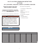
DSI Removal Kit installation shall be completed by qualified agency. Figure 1 - Sight Glass, Casting Temperature Switch,Gas Valve Igniter ! WARNING Fire, explosion, asphyxiation and electrical shock hazard. Improper installation could result in death or serious injury. Read these instructions and understand all requirements, including requirements of authority having jurisdiction, before beginning installation.
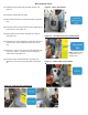
DSI Removal Conti. 5. Remove temperature sensor from thermo well, save clip. See figure 3. Figure 3 - Temperature Sensor, Clip and Well 6. Locate wire bundle going to external junction box. Cut the wire bundle. See figure 4. 7. Disconnect pressure hoses at: See figure 5. A. Gas valve - reference port B. site glass C.
DSI Removal Conti. 8. Lift, twist and remove control panel assembly. See figure 6. Figure 6 - Remove Existing Control Panel Asembly 9. Remove existing igniter. See figure 7. 10. Disconnect air intake at Fernco connection. Remove nuts holding mixing valve to casting. See figure 8.
DSI Removal Conti. 11. Remove mixing valve body and first gasket. See figure 9. Figure 9 - Mixer with Gasket 12. Remove existing burner plate. 13. Disconnect all wires connected inside the junction box. 14. Remove small conduit knockout from upper left of junction box. See figure 10. 15. Mark hole from knockout on panel for location. See figure 10. Figure 10 - Mark Knockout Hole on Sheet Metal 16. Remove two screws holding junction box. Remove junction box. Save screws and junction box for use. 17.
DSI Removal Conti. 19. Kit 550002829 (100 MBH ONLY) : A. Remove inducer assembly , 4 screws. See figure 2. B. Remove air baffle plate inside fernco fitting. See figure 8. Figure 13 - Install Replacement Junction Box HSI Installation: 1. Attach junction box to side of boiler panel with two screws. See figure 13. Figure 14 - Install Supplied Replacement Control Panel Assembly 2. Install replacement control panel assembly. See figure 14. 3. Install supplied burner plate and gasket. 4.
HSI Installation 5. Attach gas valve body. Leave nuts loose. See figure 16 Figure 16 Attach Gasket and Gas Mixing Valve 6. Install supplied hot surface igniter with two screws. Tighten all screws holding gas mixer in place. Ensure wire crimp of grounding spade is under the gasket. See figure 17. 7. Kit 550002829 (100 MBH only) : • Install supplied inducer with 4 pin connector. • Install supplied air baffle plate marked "100 S3" inside Fernco fitting. See figure 8.
HSI Installation 9. Run wire bundle with power wires to center of knock out of junction box. Snap black strain relief in place. See figure 19. Figure 19 Connect Thermostat and Power Wires 10. Run thermostat control wires to upper left knock out. Snap grey strain relief in place. See figure 19. 11. Insert supplied temperature sensor into thermo well. Ensure it is inserted in all the way. The temperature sensor serves as the LWCO and must have contact with the sidewall of the well for operation.
HSI Installation 12. Connect pressure tubes: See figure 21. A. Site glass - run tube over gas valve assembly and/or piping creating an inverted u-trap. Translucent silicone tubing coming from a tee. B. Gas valve - reference port. Clear silicone tube coming from a cross. C. Air intake. Clear silicone tube coming from the cross. 13. Wire junction box internal wires and cover plate. See figure 19.
HSI Installation Figure 23 - Label Placement 14. Install top boiler panel. 15. Turn on electric and gas to boiler 16. Resume operation using OPERATING INSTRUCTIONS found on Operating Instructions label on boiler or in Installation, Operation & Maintenance Manual. 17. Verify proper operation by following START UP PROCEDURE in Installation, Operation & Maintenance Manual. 18. Verify Combustion: A. Adjust gas pressure for optimal A/F ratio. Gas pressure and flow will be lower after kit installation.
IMPORTANT Prior to leaving job site review supplied instructions for : 1. Proper Venting Material 2. Proper Venting Size 3. Proper Venting Installation 4.
Date Service Performed Company Name & Tech Initials Company Address & Phone # SERVICE RECORD 12
DIMENSIONS Figure 1 - Boiler Dimensions NOTICE Draft inducer (blower) may be rotated 90° or 180° to orient vent connection towards right side or rear.
INTRODUCTION Dimensions.................................................................................................................... 2 Introduction................................................................................................................... 3 Important Safety Information........................................................................................... 4 Boiler Ratings & Capacities ..........................................................................................
IMPORTANT SAFETY INFORMATION General Boiler installation shall be completed by qualified agency. See glossary for additional information. Installation shall conform to requirements of authority having jurisdiction or in absence of such requirements: • United States ! WARNING • National Fuel Gas Code, ANSI Z223.1/NFPA 54. Fire, explosion, asphyxiation and electrical shock hazard. Improper installation could result in death or serious injury.
BOILER RATINGS & CAPACITIES Table 1 - SEA LEVEL RATINGS – NATURAL AND PROPANE GASES Model Input *(MBH) ++ Heating Capacity *(MBH) Net AHRI Rating *(MBH) Shipping Weight (lbs.) AFUE 90-50 50 45 39 220 90.0 90-75 75 68 59 220 90.0 90-100 100 90 78 220 90.0 * 1 MBH = 1,000 Btuh Btuh = British Thermal Units Per Hour ++ AFUE (Annual Fuel Utilization Efficiency) and Heating Capacity is based on the D.O.E. (Department of Energy) test procedure.
BOILERS FOR USE AT HIGH ALTITUDE - UNITED STATES INSTALLATIONS • Instructions on how to adjust gas manifold pressure settings see Figure 25 and Figure 26, Page 44. • Boilers (with exception of 90-75 propane (LP) product) are factory equipped for operation at altitudes ranging from 0-10,000 feet above sea level. Note 90-75 propane (LP) applications for 5,000 - 10,000 feet above sea level require orifice change as well as gas manifold pressure adjustment based upon calorific (Btu) value of supply gas.
BOILERS FOR USE AT HIGH ALTITUDE - UNITED STATES INSTALLATIONS Model 90-75 propane (LP) units only at altitudes above 5,000 ft., install 90-75 High Altitude Orifice Kit #550002629*. For all other altitudes use sea level orifice Altitude in Ft. Normal Input (MBH) Table 3 - PROPANE GAS MODEL 90-50 Stock Factory Btu Value of Propane Gas++ Settings 2300 2350 2400 2450 0-5,000 5,000-10,000 50 Altitude in Ft. Normal Input (MBH) Combustion Setting (CO2) Orifice – – – – 10.0 -11.
BEFORE INSTALLING THE BOILER Boiler Sizing 1. Boiler is equipped for residential installations. If used 2. 3. 4. 5. 6. 7. 8. 9. 10. for commercial applications, any additional code requirements must be adhered to for installation. This may require additional controls including but not limited to an additional low water cut off, a manual reset high temperature limit, and wiring and/or piping modifications. Before servicing boiler - allow boiler to cool.
BOILER INSTALLATION Locating The Boiler 1. Place crated boiler as close to selected location as Combustion Air And Vent Pipe Requirements This boiler requires a dedicated direct vent system. In a direct vent system, all air for combustion is taken directly from outside atmosphere, and all flue products are discharged to outside atmosphere. Terminate combustion air and vent pipe connections in same atmospheric pressure zone, through roof or sidewall (roof termination preferred).
BOILER INSTALLATION Condensate Drain Requirements 3. In-so-far as is practical, close all building doors and • Pitch condensate drain line down to floor drain at minimum of ¼” per foot. External condensate pump (not furnished) may be used if floor drain is not available. Installation shall conform to requirements of authority having jurisdiction, check local codes for requirements. • Condensate pump must be designed for flue gas condensate application.
NEAR BOILER PIPING Near Boiler Piping Supply And Return Lines • When boiler installation is for new heating system, install all of radiation units (panels, radiators, baseboard, or tubing) and supply and return mains. • Boiler is set up to receive 1¼” NPT supply and return piping from top access. • Boiler may be piped from left side by turning supply elbow. • After all heating system piping and components have been installed, make final connection of system piping to boiler.
NEAR BOILER PIPING Figure 2 - Single Zone Boiler Piping SAFETY RELIEF VALVE - SEE PAGE 18 FOR REQUIREMENTS 12
NEAR BOILER PIPING Multi-Zone Systems Multi-zone systems with two zones are typically piped as shown in Figures 3 or 4. Multi-zone systems with more than two zones are likely to have small zones with very low heat and flow requirements compared to full heating capacity of the boiler. This can result in very low flow in the boiler if only one small zone is calling for heat.
NEAR BOILER PIPING Figure 4 - Two Zone Boiler Piping With Circulators SAFETY RELIEF VALVE - SEE PAGE 18 FOR REQUIREMENTS 14
NEAR BOILER PIPING Figure 5 - Primary/Secondary Piping With Circulators And Domestic Hot Water 15
NEAR BOILER PIPING Figure 6 - Piping Primary/Secondary Multi Zone System Piping With Zone Valves And Domestic Hot Water (With Zone Valve) 16
NEAR BOILER PIPING Figure 7 - Piping Primary/Secondary Piping With Zone Valves And Domestic Hot Water (With Circulator) 17
NEAR BOILER PIPING ! WARNING Figure 8 - Relief Valve Boiler Piping Burn and scald hazard. Safety relief valve could discharge steam or hot water during operation. Install discharge piping per these instructions. RELIEF VALVE Safety Relief Valve Installation of safety relief valve shall conform to ANSI/ ASME Boiler and Pressure Vessel Code, Section IV. • Install furnished safety relief valve using 3/4” x 4½” pipe provided with boiler. See Figure 8.
NEAR BOILER PIPING Figure 9 - Diaphragm Type Expansion Tank Piping SAFETY RELIEF VALVE - SEE PAGE 18 FOR REQUIREMENTS 19
NEAR BOILER PIPING Figure 10 - Conventional (Closed Type) Expansion Tank Piping SAFETY RELIEF VALVE SEE PAGE 18 FOR REQUIREMENTS 20
NEAR BOILER PIPING Condensate Drain Piping Filling Condensate Trap With Water Boiler is factory equipped with a condensate trap. An additional trap is not required and should NOT be used. 1. Provide ½” PVC condensate drain and fittings. Condensate drain to be pitched down to floor drain at a minimum of ¼” per foot. Installation shall conform to requirements of authority having jurisdiction, check local codes for requirements. 2. Install ½” PVC tee to overflow fitting as shown in Figure 11. 3.
COMBUSTION AIR AND VENT PIPE 2. Canadian installations: Connections And Termination • First 3 feet (900mm) of venting must be readily available for visual inspection. • Specified primers and glues of certified vent system must be from single manufacturer, and not intermixed with other manufacturer’s vent system parts. • Components of the certified system must not be interchanged with other vent systems, or unlisted pipe and/or fittings.
COMBUSTION AIR AND VENT PIPE Table 5 - Combustion Air And Vent Piping Lengths - Total Equivalent Length BOILER SIZE 2” PIPE MINIMUM VENTING 2” PIPE MAXIMUM VENTING 3” PIPE MINIMUM VENTING 3” PIPE MAXIMUM VENTING 100 2 FEET 21 FEET 15 FEET 92 FEET 75 & 50 2 FEET 26 FEET 20 FEET 112 FEET NOTE: Follow venting lengths strictly, to avoid nuisance pressure switch trips. 5. See Figure 12 thru Figure 17, Pages 24 thru 26 6. 7. 8. 9.
COMBUSTION AIR AND VENT PIPE Installation 1. Attach combustion air intake piping using field supplied 2. 3. 4. 5. 6. 7. 8. 9. 10. Wipe excess cement from joint. Continuous bead of 2” flexible coupling. Attach vent piping to furnished 2” vent pipe connector on draft inducer outlet. All pipe joints are to be water tight Working from boiler to outside, cut pipe to required length(s). Deburr inside and outside of pipe. Chamfer outside edge of pipe for better distribution of primer and cement.
COMBUSTION AIR AND VENT PIPE Figure 13 - Side Wall Vent / Intake terminations - Less Than 12” Clearance Above Grade OVERHANG Less Than 12” Clearance 12" MINIMUM 12" MINIMUM 12" SEPARATION BETWEEN BOTTOM OF AIR INTAKE AND BOTTOM OF VENT 12" MINIMUM 90° VENT MAINTAIN 12" MIN CLEAR ABOVE HIGHEST SNOW LEVEL OR GRADE 3" MAXIMUM SEPARATION 36" MIN 15" MAX 18" MAXIMUM Figure 14 - Side Wall Vent/Intake Terminations - 12” Or More Clearance Above Grade OVERHANG 12” Or More Clearance 12" MINIMUM 12" MINIMU
COMBUSTION AIR AND VENT PIPE Figure 15 - Concentric Vent Terminations Figure 17 - Concentric Vent Roof Installation 1" (25.4mm) Maximum Vent Combustion Air 1" (25.4mm) Maximum * See Note Below Overhang 12" (305mm) Minimum 36"(0.
COMBUSTION AIR AND VENT PIPE Figure 18 - Combustion Air and Vent Piping - Boiler Connections SAFETY RELIEF VALVE SEE PAGE 18 FOR REQUIREMENTS 2” (50.8mm) Diameter Vent And Combustion Air Intake Piping - 21 ft (6.4m)maximum total equivalent length for 90-100 models -26 ft (7.9m) maximum total equivalent length for 90-50 and -90-75 models - 2 ft (0.6m) minimum total equivalent length for all models TRANSITION FITTING 2” (50.8mm) ⊘ to 3” (76.
GAS SUPPLY PIPING ! CAUTION ! WHAT TO DO IF YOU SMELL GAS • Do not try to light any appliance. Fire Hazard. Do not use matches, candles, open flames, or other methods providing ignition source. Failure to comply will result in death or serious injury. • Do not touch any electrical switch; do not use any phone in your building. • Immediately call your gas supplier from a neighbor’s phone. Follow gas supplier’s instructions. • If you cannot reach your gas supplier, call the fire department.
GAS SUPPLY PIPING Table 7 – Gas Pipe Sizes NATURAL GAS Pipe Capacity - BTU Per Hour Input Includes Fittings Length of Pipe - Ft. 1/2” 3/4” 1” 1 1/4” 20 92,000 190,000 350,000 625,000 40 63,000 130,000 245,000 445,000 60 50,000 105,000 195,000 365,000 PROPANE GAS Pipe Capacity - BTU Per Hour Input Includes Fittings Length of Pipe - Ft.
ELECTRICAL WIRING Connect Circulator Pump Wiring ! WARNING See Figure 20, Page 31 for circulator pump field wiring connections. Supplied 5 foot wiring harness with flexible metal conduit for connection from circulator pump to junction box. If two 120 Volt circulator wire terminals inside junction box are not used, leave two wire nuts to prevent short circuit. Electrical shock hazard. Turn OFF electrical power supply at service panel before making electrical connections.
ELECTRICAL WIRING Figure 20 - Field Wiring Connections SAFETY RELIEF VALVE SEE PAGE 18 FOR REQUIREMENTS 31
ELECTRICAL WIRING Figure 21 - Wiring Schematic NOTICE If any of original wire as supplied with this appliance must be replaced, it must be replaced with type 105°C Thermoplastic wire or its equivalent 32
ELECTRICAL WIRING Figure 22 - Ladder Diagram for Figure 22 33
CONTROLS AND ACCESSORIES A - Setting High Limit 1 - Integrated Boiler Control (IBC) • Integrated Boiler Control (IBC) is a microprocessor based controller for high efficiency gas boilers. To adjust, turn HI TEMP dial 1 until desired setting is displayed. Overall range of High limit setting is from 100°F to 220°F (82° C to 104° C). High limit (HL) on limit control is factory set at 190°F. Temperature setting may be varied to suit requirements of installation.
CONTROLS AND ACCESSORIES SETTING OFF Disables economy function. Will allow boiler to fire until hi-limit temp is reached and re-fire with a 10° subtractive differential. LO Provides lowest level of fuel savings. Use this setting only if the house does not stay warm at higher settings. 1 2 3 4 5 HI Recommended setting for single zone systems. Recommended setting for Two zone systems. Recommended setting for Three zone systems. Recommended setting for Four zone systems.
START UP Water Quality, Water Treatment and Freeze Protection - see Appendix A Filling Boiler With Water And Purging Air For Systems With Diaphragm Type Expansion Tanks Refer to the appropriate diagrams,“Near Boiler Piping” on page 11 for more information. 1. Close all zone service valves on the supply and return piping. Open the feed valve and fill boiler with water. Make sure air vent is open.
OPERATING INSTRUCTIONS ! WARNING ! CAUTION If you do not follow these instructions exactly, a fire or explosion may result causing property damage, personal injury or loss of life. • This appliance is equipped with an ignition device which automatically lights burner. Do NOT try to light this burner by hand. WHAT TO DO IF YOU SMELL GAS • Do not try to light any appliance. • Do not touch any electrical switch; do not use any phone in your building.
DETAILED SEQUENCE OF OPERATION SERVICE HINTS POWER ON STAND BY THERMOSTAT CALLS FOR HEAT CIRCULATOR ENERGIZES THRU 2K1 CONTACTS IF MAIN BURNER DOES NOT PROVE FLAME IN 3 TRIALS, CONTROL LOCKOUT. VALVE/FLAME LIGHT BLINKS , RESET IS REQUIRED. THIS PROBLEM IS A RESULT OF NOT ESTABLISHING FLAME SIGNAL. IBC SELFCHECK OF INTERNAL CIRCUITRY 1-2 SEC CONTROL WILL ATTEMPT 2 ADDITTIONAL IGNITION SEQUENCES. STARTING WITH PREPURGE. NO IBC CHECKS N.O.
DETAILED SEQUENCE OF OPERATION End Of Normal Sequence Of Operation Thermostat ends call for heat. Gas valve and circulator pump are de-energized, valve and flame lights go out. Blower runs for 30 seconds post purge, purge light is on. Blower is de-energized after 30 seconds, purge light shuts off. Boiler stand by for next call for heat.
DETAILED SEQUENCE OF OPERATION Sequence Of Operation Diagnostics Follow sequence using the diagnostic indicator lamps on Integrated Boiler Control (IBC). See “Controls And Accessories” on page 34 for normal sequence of operation. Detailed sequence of operation containing potential faults can be found in service hints section.
DETAILED SEQUENCE OF OPERATION DRAFT INDUCER TEMPERATURE SAFETY SWITCH If draft inducer temperature reaches temperature safety switch set-point, safety switch contacts open immediately, closing gas valve (light goes out). CASTING TEMPERATURE SAFETY SWITCH If burner operates when boiler has no water, aluminum boiler sections heat up rapidly. Casting temperature safety switch contacts will open, breaking 24 volt power to IBC. Power indicator light goes out. Requires manual reset to re-close contacts.
VERIFICATION PROCEDURE AND ADJUSTMENT Verify Proper Sequence Of Operation Measure Natural Gas Input Rate Place boiler into operation and observe operation through several cycles. Follow remaining steps in this section to insure boiler is operating correctly. First couple of cold starts may be rough due to gas line not being completely purged of air, causing low firing rate and high excess air levels.
VERIFICATION PROCEDURE AND ADJUSTMENT IV.Measure new input rate (cover screw must be installed). Repeat steps I.-IV until the input rate is within +/-2% of the nameplate input rating. V. If the actual input rate can not be set to within 2% of the correct input rating by adjusting manifold pressure, a change in gas orifice size is required. Consult the boiler manufacturer for information on correct orifice sizing.
VERIFICATION PROCEDURE AND ADJUSTMENT Figure 25 - Manifold Pressure Measurement Detail Following steps and diagram indicate location of the connection points required to measure manifold pressure. Manifold pressure may be measured using a U-Tube Manometer or Differential Pressure Gauge. Diagram shows connection of both measuring devices. Only ONE DEVICE IS REQUIRED to measure manifold pressure. Remove plug.
DIFFERENTIAL AIR PRESSURE SWITCH CHECK - ALL MODELS • Following steps and diagram indicate locations of connection points required to check differential air pressure. • Differential air pressure switch is safety device which prevents boiler from firing if there is air intake, boiler heat exchanger or vent blockage. BOILER STATUS DIFFERENTIAL PRESSURE (W.C.) PRESSURE SWITCH CONTACTS Not Running 0” Normally Open • Turn off service switch, or lower thermostat setting. 1.
NEGATIVE PRESSURE SWITCH CHECK For use on Model - 100 boilers only. • Following steps and diagram indicate locations of connection points required to check negative pressure. • Negative pressure switch is safety device which prevents boiler from firing if there is air intake blockage. • Turn off service switch, or lower thermostat setting. • Remove vinyl cap from 4-way connector. • Turn on service switch and set thermostat to call for heat.
MAINTENANCE AND CLEANING Maintenance As Outlined Below Can Be Performed By Owner Unless Otherwise Noted. 2. Check boiler area is free from combustible materials, gasoline, and other flammable vapors and liquids. 3. Circulator pump and blower motor furnished with boiler are permanently lubricated from factory and require no further lubrication. Additional or non-factory supplied pumps and/or motors should be lubricated according to the pump and/or motor manufacturer’s instruction.
MAINTENANCE AND CLEANING Annual Examination And Cleaning Of Boiler Components ! DANGER Before servicing, turn off electrical power to boiler at service switch. Close manual gas valve to turn gas supply OFF to boiler. Failure to comply will result in death or serious injury. NOTICE Have qualified service agency perform the following service procedures. Boiler owner should not attempt these procedures. 1. Before Servicing, turn off electrical power to boiler at service switch.
TROUBLESHOOTING ! WARNING 2. Troubleshooting tools: A. Voltmeter to check 120 vac and 24 vac B. Continuity tester. C. Inclined manometer or pressure gauge with 0-3.0” Range (0.01” Scale) for measuring suction pressures at pressure switch. D. U-tube manometer or differential pressure gauge with 0-14” range (0.1” Scale) for measuring inlet and manifold gas pressures. Fire, explosion or shock hazard. Do not attempt to modify the physical or electrical characteristics of this boiler in any way.
TROUBLESHOOTING - HIGH LIMIT CONTROL AND LWCO 1 HI TEMP illuminates when boiler water temperature Figure 27 - LED Legend 0 13 reaches high limit setting. Remains lit until water temperature falls 10°F below high limit setting. Limit prevents burner operation while this LED is on. 115 2 ACTIVE Indicates low water cut-off function is active. When control is installed with Electro-well, LED is on at all times when control is powered.
TROUBLESHOOTING -HYDROSTAT HIGH LIMIT CONTROL AND LWCO Troubleshooting Flow Chart Burner Will Not Fire See Flow Chart, this page. No or Insufficient Domestic Hot Water If installed with indirect water heater, insure end switch in relay box controlling indirect water heater is properly connected to Cable 2. This will insure domestic water calls are prioritized. If Cable 2 is not used, turn Economy Feature OFF. 1. Check for air-bound radiators. 2.
TROUBLESHOOTING Troubleshooting Chart 1
TROUBLESHOOTING Troubleshooting Chart 2 ! " # " " " " ! " # " ! " "
TROUBLESHOOTING Troubleshooting Chart 3 CHART 1 OPEN BLOWER STARTS NO CHECK FOR VAC NO BETWEEN TERMINALS 1 AND 3 AT CONNECTOR CN4 ON IBC YES REPLACE IBC YES CHECK FOR 120 VAC AT BLOWER LEADS ON WIRING HARNESS NO REPAIR/REPLACE WIRING FROM IBC TO BLOWER YES REPAIR/REPLACE BLOWER PRESSURE SWITCH CONTACTS OPEN IBC PURGE LIGHT ON? YES NO IBC WAITS UP TO 5 MINUTES FOR NORMALLY OPEN AIR PRESSURE SWITCH CONTACTS TO CLOSE, INDICATING BLOWER SUCTION IS PRESENT ARE ORIFICE IN NEGATIVE PRESSURE HOSE CLEAR
TROUBLESHOOTING Troubleshooting Chart 4 CHART 3 YES IGNITER/SENSOR WARMS UP AND GLOWS YELLOW/ORANGE DURING 20 SECOND WARM UP NO CHECK FOR 120 VAC BETWEEN TERMINALS 1 AND 2 AT CONNECTOR CN1 ON IBC (DURING IGNITER WARM UP) NO REPLACE IBC YES YES CHECK FOR 120 VAC AT IGNITER/SENSOR LEADS ON WIRING HARNESS (DURING IGNITER WARM UP) NO YES AFTER 20 SECOND IGNITER WARM UP, GAS VALVE IS ENERGIZED VALVE LIGHT IS ON 2 SECONDS LATER POWER IS REMOVED FROM IGNITER/SENSOR IGNITER LIGHT IS OFF DOES MAIN BURNER LIG
TROUBLESHOOTING Troubleshooting Chart 5 CHART 4 YES CHART 4 YES POSSIBLY MIXTURE TOO LEAN! CHECK GAS LINES DOWNSTREAM OF GAS VALVE FOR BLOCKAGE. ARE GAS LINES CLEAR? IS GAS/VENTURI VALVE CORRECT SIZE? SEE REPAIR PARTS DIAGRAM. NO CLEAN/REPLACE GAS LINES . BE SURE TO USE CORRECT GAS/VENTURI VALVE SIZE. YES POSSIBLY MIXTURE TOO RICH! CHECK FLUE PASSAGES IN BOILER PER "MAINTENANCE AND CLEANING".
TROUBLESHOOTING Troubleshooting Chart 6 CHART 5 YES CHART 5 NO #3 CHART 5 NO #2 REPLACE GAS CONTROL. YES CHECK GAS ORFICICE SIZE. IS GAS ORIFICE SIZE CORRECT. CHECK REPAIR PARTS LIST FOR CORRECT SIZE. IS GAS ORIFICE CLEAR OF BLOCKAGE. RUNS FOR 25-50 SECONDS, THEN TURNS OFF. CHECK FIRING RATE OF UNIT. IS UNIT FIRING AT THE CORRECT RATE? YES NO DOES THE UNIT USE LP GAS. NO ADJUST RATE AS DESCRIBED IN THE CHECK OUT PROCEDURE AND ADJUSTMENT SECTION OF THE MANUAL.
APPENDIX A - WATER QUALITY, WATER TREATMENT AND FREEZE PROTECTION Aluminum Series High Efficiency Gas-Fired Boiler DIELECTRIC ISOLATION & ANTIFREEZE PROTECTION ! WARNING Follow these instructions to prevent damage to boiler’s heat exchanger caused by inadequate dielectric isolation, incorrect water treatment or antifreeze application. Failure to comply could result in death or serious injury.
System and Operating Precautions Applies to ALL Aluminum High Efficiency Gas-Fired Water Boilers Clean System First Eliminate System Leaks BEFORE connecting boiler to heating system, clean and flush system thoroughly. Verify system is free of sediment, flux and any residual boiler water additives. Continuous addition of make-up water will constantly add oxygen to system. Eliminate all system leaks. All system leaks must be repaired immediately.
System and Operating Precautions Applies to ALL Aluminum High Efficiency Gas-Fired Water Boilers General Guidelines When Using Antifreeze • Use only antifreeze products recommended for use with aluminum boilers, as listed in this addendum. See Table 8. • Continuous addition of make-up water will dilute power of antifreeze and change buffers ability to maintain pH. • Flush old antifreeze from system. Flush boiler and system separately. • Do not use antifreeze unless required.
System and Operating Precautions Applies to ALL Aluminum High Efficiency Gas-Fired Water Boilers Table 8 - Antifreeze Products Compatible Aluminum Antifreeze & Inhibitor Suppliers Noburst AL Antifreeze Noble Company P. O. Box 350 Grand Haven, MI 49417 www.noblecompany.com Tel: 800-878-5788 Fax: 231-799-8850 Rhogard Antifreeze & Pro-Tek 922 Inhibitor* Rhomar Water Management, Inc. P. O. Box 229 Springfield, MO 65801 www.rhomarwater.