UB 90 125-200 SERIES II GAS-FIRED, DIRECT VENT, CONDENSING, HOT WATER BOILER Models UB90-125 UB90-150 UB90-175 UB90-200 INSTALLATION, OPERATION & MAINTENANCE MANUAL Manufactured by: ECR International, Inc. An ISO 9001-2008 Certified Company 2201 Dwyer Avenue, Utica NY 13504-4729 web site: www.ecrinternational.com P/N 240009432 Rev.
TABLE OF CONTENTS 1 - Boiler Ratings & Capacities..............................................................................................3 2 - Safe Installation And Operation .......................................................................................5 3 - Locating The Boiler ........................................................................................................6 5 - Combustion Air/ Vent Requirements ..........................................................................
1 -BOILER RATINGS & CAPACITIES Figure 1 - Boiler Jackets Table 1 - SEA LEVEL RATINGS (NATURAL AND PROPANE GASES) Model Input (MBH)(1) Heating Capacity (MBH)(1)(2) 125 125 113 98 284 90.0 2” CPVC & 3” PVC 150 150 134 117 284 90.0 2” CPVC & 3” PVC 175 175 158 137 284 90.0 2” CPVC & 3” PVC 200 200 180 157 284 90.0 2” CPVC & 3” PVC (1) (2) Net AHRI Rating Shipping AFUE (MBH)(1) Weight (lbs.
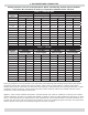
1 - BOILER RATINGS & CAPACITIES Ratings shown are for sea level applications. Boiler automatically derates input as altitude increases. No alterations to boiler are required for altitudes above sea level. Table 2 - NATURAL GAS Nominal Input 200,000 175,000 150,000 125,000 Vent Lengths Vent Lengths Vent Lengths Vent Lengths Altitude Min Max Min. Max Min. Max Min.
2 - SAFE INSTALLATION AND OPERATION Installers - Follow local regulations with respect to installation of CO (Carbon Monoxide) Detectors. Follow maintenance recommendations in this manual. See “Maintenance And Cleaning” on page 42. ! WARNING Improper installation, adjustment, alteration, service or maintenance could result in death or serious injury. Boiler Sizing • Verify you have selected the boiler with proper capacity before continuing installation.
3 - LOCATING THE BOILER Locating The Boiler 1. Select level location, central to piping systems served and close to vent and air intake terminals as possible. 2. Accessibility clearances, if more stringent (i.e. larger clearances) than required fire protection clearances, must be used for boiler installation. Accessibility clearances may be achieved with use of removable walls or partitions. 3. Clearances shown in Table 4 indicate required clearances per CSA listing.
3 - LOCATING THE BOILER 6. After it has been determined each appliance remaining connected to common venting system properly vents when tested as outlined above, return doors, windows, exhaust fans and any other gas-burning appliance to their previous condition. 7. Any improper operation of common venting system should be corrected so installation conforms with the National Fuel Code, ANSI Z223.1/NFPA 54.
4 - NEAR BOILER PIPING 1. Do not install copper supply and return piping directly 2. 3. 4. 5. 6. 7. 8. Figure 2 - Diaphragm Type Expansion Tank Piping into aluminum boiler section castings due to galvanic corrosion between dissimilar metals. Use iron, steel bushings or pipe connectors between copper system piping and boiler to make final connection to boiler. Use of dielectric unions is acceptable, installer supplied.
4 - NEAR BOILER PIPING Safety Relief Valve / Temperature Pressure Gauge Boiler is furnished with safety relief valve and temperature pressure gauge. • Install safety relief valve using pipe fittings provided with boiler. Figure 3, Page 8. • Install safety relief valve with spindle in vertical position. • Do not install shutoff valve between boiler and safety relief valve. • Install discharge piping from safety relief valve. A. Use ¾” or larger pipe. B.
4 - NEAR BOILER PIPING Condensate Drain Requirements Pitch condensate drain line down to floor drain at minimum of ¼” per foot (21mm/m). External condensate pump (not furnished) may be used if floor drain is not available. Condensate pump must be designed for flue gas condensate application. Condensate trap is proved with boiler. 1. Build condensate trap in the field. See Figure 7. 2. Wood frame or blocks may be used to raise boiler to maintain drain pitch or to be above external condensate pump reservoir.
5 - COMBUSTION AIR/ VENT REQUIREMENTS Combustion Air/Vent Pipe Requirements Boiler requires dedicated direct vent system. Direct vent system, all air for combustion is taken directly from outside atmosphere, and all flue products are discharged to outside atmosphere. Combustion air and vent pipe connections must terminate together in same atmospheric pressure zone, either through roof or sidewall (roof termination preferred). See Figures 8 and 9 for required clearances.
5 - COMBUSTION AIR/ VENT REQUIREMENTS ! WARNING Figure 12 - Concentric Vent Roof Installation Fire, explosion, asphyxiation hazard. Solvent cements are combustible. Keep away from heat, sparks, or open flame. Use only in well ventilated areas. Avoid breathing in vapor or allowing contact with skin or eyes. Improper installation could result in death or serious injury. Read this manual and understand all requirements before beginning installation.
6 - COMBUSTION AIR AND VENT PIPE Connections And Termination To prevent damage to gas burner and ensure proper operation of unit, installer must clean and remove all shavings from interior of all PVC pipe used on air intake. Boilers require dedicated direct vent system. All air for combustion is taken directly from outdoors through combustion air intake pipe. All flue products are discharged to outdoors through vent pipe. Install vent system in accordance with these instructions. 1.
6 - COMBUSTION AIR AND VENT PIPE NOTICE Exhaust transition from 2” pipe to 3” pipe must be made in vertical run. (Transition pieces not included.) 5. Consider following when determining appropriate location for termination of combustion air and vent piping: A. Position termination where vent vapors will not damage plants/shrubs, air conditioning equipment, or siding on the house. B. Position termination so it will not be effected by wind eddy, air born leaves, snow, or recirculated flue gases. C.
7 - GAS SUPPLY PIPING Check Gas Supply 5. Use two pipe wrenches when making connection to Table 5 - Gas Supply Pressure Pressure Natural Gas Propane Gas Minimum 4” w.c. 10” w.c. Maximum 10” w.c. 14” w.c. 6. 7. 8. Please check line pressure while unit is running. • Gas pipe to boiler must be correct size for length of run and total Btuh input of all gas utilization equipment connected to it. 9. 10. 11. • See Tables 6 and 7 for proper size.
8 - ELECTRICAL WIRING ! WARNING Figure 15 - Field Wiring Connection Electrical shock hazard. Turn OFF electrical power supply at service panel before making electrical connections. Failure to do so could result in death or serious injury. NOTICE Use copper conductors only. Electrically bond boiler to ground in accordance with requirements of authority having jurisdiction. Refer to National Electrical Code, ANSI/NFPA 70.
8 - ELECTRICAL WIRING AVOID THE FOLLOWING Dead Spots Corners Alcoves Behind doors Cold Spots Concealed pipes or ducts Stairwells - drafts Unheated rooms on the other side of the wall Hot Spots Concealed pipes Fireplaces TVs or radios Lamps Direct sunlight Kitchens Thermostat Installation • Follow instructions included with your thermostat. • Locate thermostat five feet above floor on inside wall. • Mount directly on wall or vertically mount on outlet box.
8 - ELECTRICAL WIRING Figure 16 - Schematic Wiring Connections NOTE: If any of the original wire as supplied with this appliance must be replaced, it must be replaced with type 150°C Thermoplastic wire or its equivalent.
8 - ELECTRICAL WIRING Figure 17 - Ladder Wiring Diagram NOTE: If any of the original wire as supplied with this appliance must be replaced, it must be replaced with type 150°C Thermoplastic wire or its equivalent.
9 - CONTROLS AND ACCESSORIES See “Troubleshooting” on page 34 for detailed sequences of operation and troubleshooting procedures. See separately provided “Repair Parts Manual” for locations of control components and accessories described. Figure 19 - Indicator Lights Integrated Boiler Control (IBC) • Integrated Boiler Control (IBC) is a microprocessor based controller for high efficiency gas boilers.
9 - CONTROLS AND ACCESSORIES Differential Pressure Switches • Diaphragm type differential pressure switches are connected by vinyl tubing to gas valve, air inlet connection on negative side, and sight glass adapter on positive side. Pressure switches monitor air flow by sensing differential pressure measured in inches of water (” w.c.). • Switch factory settings are 0.5” w.c. on normally open switch and 3.5” w.c. for normally closed switch. • See pages 25-27, “Detailed Sequence of Operation,” for details.
10 - STARTUP Water Treatment And Freeze Protection - See Appendix A Filling Boiler With Water And Purging Air For Systems With Diaphragm Type Expansion Tanks Refer to the appropriate diagrams “Near Boiler Piping” on page 8 and 9. 1. Close all zone service valves on supply and return piping. Open feed valve and fill boiler with water. Verify air vent is open. Hold relief valve open until water runs air free for five seconds to rapidly bleed air from boiler, let relief valve snap shut. 2.
10 - STARTUP ! WARNING If you do not follow these instructions exactly, a fire or explosion may result causing property damage, personal injury or loss of life. • This appliance is equipped with an ignition device which automatically lights burner. Do NOT try to light this burner by hand. • Before operating smell all around appliance area for gas. Be sure to smell next to floor because some gas is heavier than air and will settle to the floor. • Use only your hand to turn the gas shutoff valve.
10 - STARTUP If Burner Appears To Pulsate During Ignition: 1. Turn off boiler power. Shut off gas supply to boiler. 2. Take burner assembly apart by removing combustion air blower and gas valve/venturi assembly from boiler. Visually inspect inside of burner. Look for debris (PVC shavings, etc.). Remove debris if present. 3. Reassemble burner assembly, turn gas supply and boiler power back on, relight boiler. If Burner Continues To Pulsates Or Fails To Light: 1.
11 - DETAILED SEQUENCE OF OPERATION DRAFT INDUCER TEMPERATURE SAFETY SWITCH If draft inducer temperature reaches temperature safety switch set-point, safety switch contacts open immediately, closing gas valve (light goes out). CASTING TEMPERATURE SAFETY SWITCH If burner operates when boiler has no water, aluminum boiler sections heat up rapidly. Casting temperature safety switch contacts will open, breaking 24 volt power to IBC. Power indicator light goes out. Requires manual reset to re-close contacts.
11 - DETAILED SEQUENCE OF OPERATION End Of Normal Sequence Of Operation Thermostat ends call for heat. Gas valve and circulator pump are de-energized, valve and flame lights go out. Blower runs for 30 seconds post purge, purge light is on. Blower is de-energized after 30 seconds, purge light shuts off. Boiler stand by for next call for heat.
11 - DETAILED SEQUENCE OF OPERATION SERVICE HINTS POWER ON STAND BY THERMOSTAT CALLS FOR HEAT CIRCULATOR ENERGIZES THRU 2K1 CONTACTS IF MAIN BURNER DOES NOT PROVE FLAME IN 3 TRIALS, CONTROL LOCKOUT. VALVE/FLAME LIGHT BLINKS , RESET IS REQUIRED. THIS PROBLEM IS A RESULT OF NOT ESTABLISHING FLAME SIGNAL. IBC SELFCHECK OF INTERNAL CIRCUITRY 1-2 SEC CONTROL WILL ATTEMPT 2 ADDITTIONAL IGNITION SEQUENCES. STARTING WITH PREPURGE. NO IBC CHECKS N.O.
12 - SEQUENCE OF OPERATION DIAGNOSTICS Sequence Of Operation Diagnostics Follow sequence using the diagnostic indicator lamps on Integrated Boiler Control (IBC). See “Controls And Accessories” on page 20 for normal sequence of operation. Detailed sequence of operation containing potential faults can be found in service hints section. SEQUENCE OF OPERATION DIAGNOSTIC INDICATOR LAMPS A. z B. | (2) Thermostat calls for heat, energizing system circulator. C.
13 - CHECKOUT PROCEDURE & ADJUSTMENTS Inspect Venting & Air Intake System - Operate boiler. Verify all vent/air intake connections are gas-tight and water-tight. Repair any leaks immediately. Inspect Condensate Drain - Verify all connections are watertight, and condensate flows freely. Repair any leaks immediately. Inspect System Piping - Verify all connections are watertight. Repair any leaks immediately. Test Ignition System Safety Shutoff 1. Turn off manual gas shut off valve. 2.
13 - CHECKOUT PROCEDURE & ADJUSTMENTS Adjustments And Checkout Appliance should operate between 8.5 And 10% CO2. Verify boiler is operating in this range. Follow steps below. NOTICE Under all conditions CO levels should not exceed 100ppm. 1. Check incoming gas pressure to appliance using Set Thermostat To Desired Temperature Set thermostat to desired room temperature and observe several complete cycles to verify proper operation.
14 - TROUBLESHOOTING - HIGH LIMIT CONTROL AND LWCO LED Legend and LWCO Test Button Figure 20 1 HI TEMP illuminates when boiler water temperature reaches high limit setting. Remains lit until water temperature falls 10°F. Limit prevents burner operation while this LED is on. 2 LWCO ACTIVE Indicates low water cut-off function is active. When control is installed with Electro-well, LED is on at all times when control is powered.
15 - TROUBLESHOOTING -HIGH LIMIT CONTROL AND LWCO Troubleshooting Flow Chart Burner Will Not Fire See Flow Chart, this page. No or Insufficient Domestic Hot Water If installed with indirect water heater, insure end switch in relay box controlling indirect water heater is properly connected to Cable 2. This will insure domestic water calls are prioritized. If Cable 2 is not used, turn Economy Feature OFF. 1. Check for air-bound radiators. 2.
15 - TROUBLESHOOTING ! WARNING Fire, explosion or shock hazard may cause death or serious injury. Do not attempt to modify physical or electrical characteristics of this boiler in any way. • • • • • • • In reset from lockout condition, all electrical meter readings at gas control valve (24 vac) must be taken within trial for ignition period. If any component dose not function properly, make sure it is correctly installed and wired before replacing.
15 - TROUBLESHOOTING System Status Indicator lights track operating sequence. If system locks out, lights indicate point in sequence of operation were lockout occurs. Refer to following pages for detailed troubleshooting procedures. LIGHT POWER STATUS INDICATES ON IBC is energized through 24 volt transformer. OFF IBC is not energized. Blinking IBC receives more than 40 VAC. ON IBC is energizing draft inducer and air flow is proven.
15 - TROUBLESHOOTING Troubleshooting Chart 1
15 - TROUBLESHOOTING Troubleshooting Chart 2 ! " # " " " " ! " # " ! " "
15 - TROUBLESHOOTING Troubleshooting Chart 3 CHART 1 OPEN BLOWER STARTS NO CHECK FOR VAC NO BETWEEN TERMINALS 1 AND 3 AT CONNECTOR CN4 ON IBC YES REPLACE IBC YES CHECK FOR 120 VAC AT BLOWER LEADS ON WIRING HARNESS NO REPAIR/REPLCE WIRING FROM IBC TO BLOWER YES REPAIR/REPLACE BLOWER PRESSURE SWITCH CONTACTS OPEN PURGE LIGHT ON? YES NO IBC WAITS UP TO 5 MINUTES FOR NORMALLY OPEN AIR PRESSURE SWITCH CONTACTS TO CLOSE, INDICATING BLOWER SUCTION IS PRESENT ARE VENT PIPE AND AIR INTAKE PIPE CLEAR (NO
15 - TROUBLESHOOTING Troubleshooting Chart 4 CHART 3 YES IGNITER/SENSOR WARMS UP AND GLOWS YELLOW/ORANGE DURING 20 SECOND WARM UP NO CHECK FOR 120 VAC BETWEEN TERMINALS 1 AND 2 AT CONNECTOR CN1 ON IBC (DURING IGNITER WARM UP) NO REPLACE IBC YES YES CHECK FOR 120 VAC AT IGNITER/SENSOR LEADS ON WIRING HARNESS (DURING IGNITER WARM UP) NO YES AFTER 20 SECOND IGNITER WARM UP, GAS VALVE IS ENERGIZED VALVE LIGHT IS ON 2 SECONDS LATER POWER IS REMOVED FROM IGNITER/SENSOR IGNITER LIGHT IS OFF DOES MAIN BURNE
15 - TROUBLESHOOTING Troubleshooting Chart 5 #% * $ #% * $ ! $$ * )%&# % $ $ ( $%# $ ' ' # # $ $ # $ $ ' %&# ' ' ## % $ + $ # ! # ! #%$ # # ! $ $ $&# % &$ ## % $ ' %&# ' ' $ + * $ ! $$ * %&# % # & ! $$ $ # ! # % # & ! $$ $ # # & ! $$ $ ! # % $%#& % $
15 - TROUBLESHOOTING Troubleshooting Chart 6 CHART 5 YES CHART 5 NO #3 CHART 5 NO #2 REPLACE GAS CONTROL. YES CHECK GAS ORFICICE SIZE. IS GAS ORIFICE SIZE CORRECT. CHECK REPAIR PARTS LIST FOR CORRECT SIZE. IS GAS ORIFICE CLEAR OF BLOCKAGE. RUNS FOR 25-50 SECONDS, THEN TURNS OFF. CHECK FIRING RATE OF UNIT. IS UNIT FIRING AT THE CORRECT RATE? YES NO DOES THE UNIT USE LP GAS. NO ADJUST RATE AS DESCRIBED IN THE CHECK OUT PROCEDURE AND ADJUSTMENT SECTION OF THE MANUAL.
15 - TROUBLESHOOTING Differential Air Pressure Switch Check Figure 21 - Locations Of Connection Points Required To Check Differential Air Pressure Differential air pressure switch is safety device which prevents boiler from firing if there is air intake, boiler heat exchanger or vent blockage. Following steps and diagram indicate location of connection points required to measure offset pressure using inclined Manometer or Differential pressure gauge. Only one device is required to measure offset pressure.
16 - MAINTENANCE AND CLEANING Acidic nature of flue gasses condensing on aluminum boiler sections cause formation of aluminum oxide. This oxide formation is normal, is generally uniform throughout boiler sections, and represents negligible mass of aluminum that is consumed by oxidation during life of boiler. If left unchecked, this buildup may eventually cause blockage of flue gas passages in boiler sections, reducing efficiency, and ultimately shutting down boiler due to lack of combustion air flow.
16 - MAINTENANCE AND CLEANING H. Aluminum oxide deposits are water soluble and may be rinsed away with spraying or running water. I. Use flexible handle nylon brush to loosen sediment and aluminum oxide on all exposed heating surfaces of boiler. Take care brush does not get stuck in heat exchanger. J. After brushing and rinsing, remove any remaining loosened sediment using vacuum with snorkel attachment. K. Inspect burner for foreign matter in flame ports or inside burner.
APPENDIX A - DIELECTRIC ISOLATION & ANTIFREEZE PROTECTION Aluminum Series High Efficiency Gas-Fired Boiler DIELECTRIC ISOLATION & ANTIFREEZE PROTECTION ADDENDUM ! WARNING ! WARNING You MUST follow these instructions to prevent damage to boiler’s heat exchanger caused by inadequate dielectric isolation, incorrect water treatment or antifreeze application. Failure to comply could result in possible severe personal injury, death or substantial property damage.
System and Operating Precautions Applies to ALL Aluminum High Efficiency Gas-Fired Water Boilers Clean the System First BEFORE connecting boiler to heating system, clean and flush system thoroughly. Verify system is free of sediment, flux and any residual boiler water additives. Eliminate System Leaks Systems having antifreeze not recommended must be completely flushed to ensure no old antifreeze remains.
System and Operating Precautions Applies to ALL Aluminum High Efficiency Gas-Fired Water Boilers General Guidelines When Using Antifreeze • Use only antifreeze products recommended for use with aluminum boilers, as listed in this addendum. See Table 1. • It is recommended that pH reading be taken annually, and adjusted as necessary. Follow antifreeze/inhibitor manufacturer’s instructions for details on how to adjust pH.
System and Operating Precautions Applies to ALL Aluminum High Efficiency Gas-Fired Water Boilers Table 9 Antifreeze Products Compatible Aluminum Antifreeze & Inhibitor Suppliers Noburst AL Antifreeze Noble Company P. O. Box 350 Grand Haven, MI 49417 www.noblecompany.com Tel: 800-878-5788 Fax: 231-799-8850 Rhogard Antifreeze & Pro-Tek 922 Inhibitor* Rhomar Water Management, Inc. P. O. Box 229 Springfield, MO 65801 www.rhomarwater.
ECR International 2201 Dwyer Avenue, Utica NY 13501 web site: www.ecrinternational.