XEB PRODUCT LITERATURE SERIES Gas-Fired Hot Water Induced Draft BOILERS INSTALLATION INSTRUCTIONS These instructions must affixed on or adjacent to the boiler. MODELS XEB-2 XEB-3 XEB-4 XEB-5 This boiler cannot be used with all types of chimneys. Read these instructions carefully before installing. These Gas-Fired Hot Water Boilers are low pressure, sectional cast iron boilers Design Certified by C.S.A. (Canadian Standards Association) for use with Natural and Propane Gases.
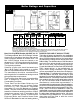
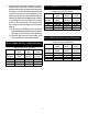
Boiler Ratings and Capacities FIG.
Before You Start Check to be sure you have the right size boiler before starting the installation. See rating and capacity table on previous page. Also be sure the new boiler is for the type of gas you are using. Check the rating plate on the right side of the boiler. You must see that the boiler is supplied with the correct type of gas, fresh air for combustion, and a suitable electrical supply.
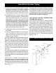
Locating the Boiler If your boiler is part of a planned heating system, boiler on Combustible Floor Base No 14614031 locate it where shown on your plan. If boiler is to for 2-5 section boilers, or No. 14614032 for 6-7 be part of an existing system, it is usually best to section boilers. We use a 2" cloudlet pad as a put it where the old one was. If you plan to change combustible floor base. These are available from location, you will need additional materials as well your localsupplier.
Fresh Air for Combustion Provision for combustion and ventilation air must be in accordance with Section 5.3, Air for Combustion and Ventilation, of the National fuel Gas Code, ANSI Z223.1-latest revision, or applicable provisions of the local building codes. WARNING Be sure provide enough fresh air for combustion. Enough air insures proper combustion and assures that hazard will develop due to the lack oxygen.
2. One permanent opening commencing with 12 inches of the top of the enclosure, shall be permitted where the equipment has clearance of at least 1 inch from the sides and back and 6 inches form the front of the appliance. The opening shell directly communicate with the outdoors or shall communicate through a vertical or horizontal duct to the outdoors or spaces (crawl or attic) that freely communicate with the out doors, and shall have a minimum free area of: a) 1 sq.
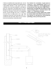
Installation-System Piping 1. Place boiler in the selected location (as near chimney as possible). Your boiler is shipped assembled. You need only to install the circulator, ball valves the relief valve with a drain line to carry any water to a drain, and the drain valve.
FIG. 7 - PIPING ARRANGEMENTS FOR BOILER WHEN USED IN CONNECTION WITH REFRIGERATION SYSTEM FIG.
Chimney and Vent Pipe Connection For boilers for connection to gas vents or chimneys, vent installations shell be in accordance with Part 7, Venting of Equipment, of the National Fuel Gas Code, ANSI Z223.1-latest issue and applicable provisions of the local building codes. CHECK YOUR CHIMNEY 5. Outside chimneys should not be used unless they are either: a. enclosed in a chase, or b. Iined with Type B vent pipe, or listed flexible vent liner, or other certified chimney lining system. 6.
If boiler is installed with single wall vent, it must have a 6" clearance between its surface and any combustible material. A new Type B gas vent orflexible liner must be installed in accordance with the instructions furnished with the vent. Maintain clearances as specified for the vent pipe. For boilers for connection to gas vents or chimneys, vent installations shall be in accordance with Part 7, Venting Equipment, of the national Fuel Gas Code, ANSI Z223.
REMOVING EXISTING BOILER FROM 4. Place in operation the appliance being inspected. COMMON VENTING SYSTEM Follow the lighting instructions. Adjust thermostat When an existing boiler is removed from a common venting system, the common venting system is likely to be too large for proper venting of the appliances remaining connected to it.
FIG. 9 - HORIZONTAL VENTING INDUCED DRAFT HIGH EFFICIENCY BOILERS Maximum Horizontal Vent Length For Stainless Steel Vent Pipe - 30 Plus One 90º Elbow Plus Vent Terminal Minimum Horizontal Vent Length - 2 Plus One 90º Elbow Vent Termination Additional elbows are equivalent to 6 feet of straight pipe for 4 diameter 90º elbow or 3 feet of straight pipe for 3 diameter 90º elbow 2, 3, 4, 5, Section Boilers use 3 vent pipe. 6, 7 Section Boilers use 4 vent pipe. CHOICE OF VENT PIPE MATERIAL a) U.L.
Horizontal Venting Instructions 1. These boilers may be vented horizontally as 6. Vent Termination Fitting: For all vent pipe materials, you may use either: shown in Fig. 9. The vent pipe is pitched down a) a 90° elbow pointing down, fitted with a from the boiler to the vent termination. Do not minimum 1/4" mesh screen to keep out connect other appliances to this vent. rodents and birds. The elbow shall be of the 2. Vent Pipe Material: same material and size as vent pipe.
c) For single wall pipe through non-combustible walls, the hole through the wall need only be large enough to maintain the pitch of the vent pipe, and provide proper sealing. A thimble is not required for single wall pipe passing through noncombustible walls. d) The venting system shall terminate at least 3 feet above any forced air inlet located within 10 feet.
B. For Heat-Fab Saf-T-Vent stainless steel vent pipe use a high temperature red silicone sealant rated for 500°F The outside of the male end and inside of the female end of the pipe must be cleaned before applying the silicone bead. For 3" vent pipe runs, the male end of the vent pipe which goes over the outlet of the boilers induced draft blower must be crimped. The vent pipe should be crimped as minimal as possible to provide a tight fit over the outlet. After crimping is completed C.
3) Insert the male end of one into the female end of the other. Push the pipe together so the female end rests up against the stop bead of the male end. 4) Insert a StaR-Joiner Band into the inlet of the beaded channel. Feed the Joiner Band in so it makes its way around the pipe, back to the channel inlet and it overlaps itself by about 1/2". 5) Cut the excess Joiner Band so it lays flat in the beaded channel. Fill the inlet of the beaded channel with high temperature silicone.
d) ProTech stainless steel vent piping requires one loose fitting FasNSeal support strap (#FSSH) for every 6' of horizontal vent. 10. If the horizontal vent must go through a crawl space or other unheated space, the cool temperatures will likely cause the flue gases to continuously condense inside the vent pipe. Do not insulate the vent pipe. It must be visible for monthly inspection.
Gas Supply Piping CHECK GAS SUPPLY The gas pipe to your boiler must be the correct size for the WARNING length of the run and for the total BTU per hour input of all Never use a match or open flam to test for leaks. gas utilization equipment connected to it. See Fig. 10 for the proper size. Be sure your gas line complies with local codes and gas company requirements. FIG.
Electrical Wiring INSTALL YOUR THERMOSTAT The thermostat location has an important effect on the operation of your boiler system. BE SURE TO FOLLOW THE INSTRUCTIONS INCLUDED WITH YOUR THERMOSTAT Locate the thermostat about five feet above the floor on an inside wall. It may be mounted directly on the wall or on a vertically mounted outlet box.
FIG. 12 - WIRING DIAGRAMS FOR HOT WATER BOILERS INTERMITTENT IGNITION IF ANY OF THE ORIGINAL WIRE AS SUPPLIED WITH THIS APPLIANCE MUST BE REPLACED, IT MUST BE REPLACED WITH TYPE 105° C THERMOPLASTIC WIRE OR ITS EQUIVALENT. NOTE: The circulator harness is factory wired to the aquastat. This harness needs to be connected to the circulator in the field.
Equipment and Optional Accessories - What They Do RELIEF VALVE You must have a relief valve on your boiler. Water expands as it is heated. If there is no place for the water to expand into, water pressure will build up inside the boiler and system. Should this happen, the Relief Valve will automatically open at a predetermined pressure. This will relieve the strain on the boiler and system.
WATER TEMPERATURE CONTROL The water temperature limit control in the relay is adjustable and may be set as necessary. It may be set as low as 140° F, or as high as 240° F This depends on the type and amount of radiation involved and weather conditions. pressure switch operates the intermittent pilot and gas valve. The air pressure switch is factory set and will only work when the blower operates properly.
Starting Your Boiler HOW A HOT - WATER SYSTEM OPERATES Your entire heating system (boiler, piping and radiation units) is filled with water. As the water in the boiler is heated, it is pumped from the top of the boiler through the supply main to the radiation units. The cooler water in them flows back through the return main to the boiler. This provides positive and rapid response to the thermostat. FOR YOUR SAFETY READ THIS BEFOR OPERATING 1.
OPERATING INSTRUCTIONS 1. Set the thermostat to lowest setting. 2. Turn off all electric power to the appliance. 3. This appliance is equipped with an ignition device which automatically lights the burner. Do not attempt to light the burner by hand. 4. Remove burner access panel. 5. Depress gas control knob slightly and turn clockwise to OFF position. FIG. 13 6. WARNING: Wait five (5) minutes to allow any gas in the combustion chamber to vent.
Checking and Adjusting GAS VALVE SAFETY SHUTDOWN TEST to see if it shuts off the gas supply to the With main burners firing, disconnect the ignition cable from the intermittent pilot control box. The gas valve should shut off the main burners. TURN OFF ELECTRIC POWER to boiler before reconnecting ignition cable, to prevent electric shock. ADJUST PILOT BURNER 1. Remove screw cover over pilot adjusting screw. 2. Insert small screwdriver and adjust flame as needed. (Fig. 14).
Maintaining Your Boiler BURNERS A visual check of the pilot and main burner flames should be made at least once each year, preferably at the beginning of the heating season. See page 17 and Figures 14, 15 and 16. RELIEF VALVE This valve should open automatically if the system pressure exceeds the pressure rating (usually 30 psi) of the relief valve. Should it ever fail to open under this condition, shut down your system.
C L E A N I N G Y O U R B O I L E R A N D sealant or equivalent). Reseal seams between adjacent sections where necessary. All joints must BURNERS Flue passages between sections should be examined yearly and cleaned if necessary. To clean, remove burners, pilot and vent pipe. Remove top and front jacket panels. Split the silicone seal on the flue collector and the clean out plates with a razor knife. Remove flue collector. Remove clean out plates by tapping upwards on the bottom of the plate with a hammer.
Service Hints You may avoid inconvenience and service calls by checking these points before you call for service. FOR YOUR SAFETY WHAT TO DO IF YOU SMELL GAS 1. Do Not try to light any appliance. 2. Do not touch any electric switch, do not use the phone. 3. Leave the building immediately, then call your gas supplier. 4. If you cannot reach the gas supplier, call the fire department. IF YOUR SYSTEM IS NOT HEATING OR NOT GIVING ENOUGH HEAT . . .
Repair Parts IMPORTANT - READ THESE INSTRUCTIONS BEFORE ORDERING All parts listed in the following Parts List may be ordered through your nearest supplier. When ordering parts, first obtain the Model Number from the data plate on your boiler, then determine the Part No.(not the Key No.) and the Description of each part from the following illustrations and list. Be sure to give us all this information: The Part No. - The Part Description The Boiler Motel No.
Repair Parts FOR USE WITH NATURAL GAS ONLY NOTE: Actual gas valve may look different than gas valve shown NATURAL GAS BURNER & MANIFOLD PARTS THIS IS A REPAIR PARTS LIST - NOT A PACKING LIST 3$57 180%(56 )25 .
Repair Parts 3$57 180%(56 )25 '(6&5,37,21 .
Repair Parts BOILER CONTROLS AND PIPING .