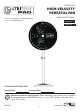
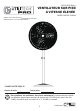
ITEM #0758414 HIGH-VELOCITY PEDESTAL FAN MODEL #SFSE-750SWA Utilitech & UT Design® is a registered trademark of LF, LLC. All Rights Reserved. Français p. 11 9 Español p. 17 ATTACH YOUR RECEIPT HERE Serial Number Purchase Date Questions, problems, missing parts? Before returning to your retailer, call our customer service department at 1-866-994-4148, 8 a.m. - 6 p.m., EST, Monday - Thursday, 8 a.m. 5 p.m., EST, Friday. AB15770 1 Lowes.
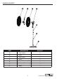
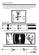
PACKAGE CONTENTS A B C D E F G PART DESCRIPTION QUANTITY A Front Guard 1 B Blade 3 C D E Rear Guard Motor 1 1 Upper Connecting Pole 1 F Standing Pole 1 G Base 1 2 Lowes.
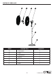
HARDWARE CONTENTS (shown actual size) AA BB CC DD EE M5x6 M6 φ12 M6x12 Screw Nut Bushing Screw Qty.3 Qty.1 Qty.1 Qty.5 FF FF GG M8 Nut Qty.1 φ15 Bushing Qty.1 M6x45 Bolt Qty.1 SAFETY INFORMATION HH II JJ KK LL φ5 M5×3.5 φ18 Spring Nut Bowl Washer M6x16 Washer Qty.4 Qty.4 Screw Qty.4 Qty.2 M8x45 Bolt Qty.1 READ AND SAVE THESE INSTRUCTIONS Please read and understand this entire manual before attempting to assemble, operate or install the product.
ASSEMBLY INSTRUCTIONS 1. Insert 5 M6×12 screws (AA) through the holes in the standing pole (F), then attach the standing pole to the base (G). 1 F F AA G HARDWARE USED AA M6×12 Screw x5 2. Loosen and remove the 3 M5x6 screws (BB) on the height adjusting base on the upper connecting pole (E). Place the spring into the standing pole (F). Insert the upper connecting pole (E) into the standing pole (F), making sure the holes on the height adjusting base and the standing pole (F) are aligned.
ASSEMBLY INSTRUCTIONS 3. Insert 1 M6x45 bolt (EE) into the hole on the neck bearing found on the motor (D) and into the top of the upper connecting pole (E), then secure them together using a bushing (DD) and M6 nut (CC). Insert 1 M8x45 bolt (HH) through the hole in the neck bearing and into the top of the upper connecting pole, then secure them using 1 bushing (GG) and 1 M8 nut (FF).
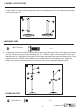
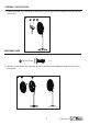
ASSEMBLY INSTRUCTIONS 5. Attach the blade (B) to the shaft on the motor (D), then secure them together using two M6x16 screws (LL). 5 B LL D HARDWARE USED LL M6x16 Screw x2 6. Attach the front guard (A) to the rear guard (C) and secure the together using the clips on the front guard. 6 A C 6 Lowes.
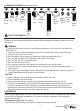
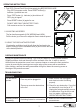
OPERATING INSTRUCTIONS 1. Test GFCI (Ground Fault Circuit Interrupter) plug BEFORE EACH USE. . Plug GFCI into power outlet. Press RESET button (b). 1 Indicator (a) should turn red. . Press TEST button (c). Indicator (a) should turn off. GFCI plug is tripped. . Press RESET button (b) again for use. . DO NOT USE FAN IF ABOVE TEST FAILS. Call customer service for assistance. b a c 2. ADJUSTING AIR SPEED The fan has three speeds (LOW, MEDIUM and HIGH).
WARRANTY ONE-YEAR LIMITED WARRANTY. The manufacturer warrants this product to be free from manufacturing defects in material and workmanship. This warranty does not cover transit damages. This warranty does not apply to damagesfrom accident, misuse, alteration of any kind to the fan or where the connected voltage is more than the nameplate voltage. This warranty does not apply to the finish on any portion of the product. Servicing performed by unauthorized persons shall render the warranty invalid.
ARTICLE #0758414 VENTILATEUR SUR PIED À VITESSE ÉLEVÉE MODÈLE #SFSE-750SWA Utilitech et le motif UT® sont des marques de commerce déposées de LF, LLC.Tous droits réservés. JOIGNEZ VOTRE REÇU ICI Numéro de série Date d’achat Des questions, des problèmes, des pièces manquantes? Avant de retourner l’article au détaillant, appelez notre service à la clientèle au 1 866 994-4148, entre 8 het 18 h (HNE), du lundi au jeudi, ou entre 8 h -et 17 h (HNE) le vendredi. 9 Lowes.
CONTENU DE L’EMBALLAGE A B C D E F G PIÈCE DESCRIPTION QUANTITÉ A Grille avant 1 B Pale 3 C D E Grille arrière Moteur 1 1 Tige de jonction supérieure 1 F Tige verticale 1 G Base 1 10 Lowes.
QUINCAILLERIE INCLUSE (grandeur réelle) AA BB CC DD EE Vis Écrou Bague M5 de 6 mm M6 de Vis φ12 Qté: 3 Qté : 1 M6 de12 mm Qté : 1 Qté : 5 FF FF Écrou M8 Qté : 1 GG Rondelle à ressort de φ5 Qté : 1 HH II JJ KK LL Rondelle Rondelle à ressort Écrou cuvette de M5 de 3,5 mm de φ5 Qté : 4 φ18 Vis Qté : 4 Qté : 4 M6 de16 mm Qté : 2 Boulon M6 de 45 mm Qté : 1 Boulon M8 de 45 mm Qté : 1 CONSIGNES DE SÉCURITÉ VEUILLEZ LIRE ET CONSERVER CES INSTRUCTIONS.
INSTRUCTIONS POUR L’ASSEMBLAGE 1. Insérez 5 vis M6 de 12 mm (AA) dans les trous de la tige verticale (F), puis fixez la tige verticale à la base (G). 1 F F AA G QUINCAILLERIE UTILISÉE AA Vis M6 de 12mm x5 2. Desserrez et retirez les 3 vis M5 de 6 mm (BB) de la base d’ajustement de la hauteur sur la tige de jonction supérieure (E). Placez le ressort dans la tige verticale (F).
INSTRUCTIONS POUR L’ASSEMBLAGE 3. Insérez un boulon M6 de 45 mm (EE) dans le trou du roulement de collet situé sur le moteur (D) et dans le haut de la tige de jonction supérieure (E), puis fixez-les à l’aide d’une bague (DD) et d’un écrou M6 (CC). Insérez un boulon M8 de 45 mm (HH) à travers le trou du roulement de collet et dans le haut de la tige de jonction supérieure, puis fixez-les à l’aide d’une bague (GG) et d’un écrou M8 (FF).
INSTRUCTIONS POUR L’ASSEMBLAGE 5. Attachez les pales (B) à la tige sur le moteur (D), puis fixez-les à l’aide de deux vis M6 de 16mm (LL). 5 B LL D QUINCAILLERIE UTILISÉE LL Vis M6 de 16 mm x2 6. Attachez la grille avant (A) à la grille arrière (C) et fixez-les à l’aide des pinces sur la grille avant. 6 A C 14 Lowes.
MODE D’EMPLOI 1. Vérifiez la fiche avec disjoncteur différentiel AVANT CHAQUE UTILISATION. . Branchez la fiche avec disjoncteur différentiel sur la prise 1 électrique. Appuyez sur le bouton « RESET » (b). Le voyant a (a) devrait devenir rouge. . Appuyez sur le bouton « TEST » (c). Le voyant (a) devrait s’éteindre. La fiche avec disjoncteur différentiel se déclenche. . Appuyez de nouveau sur le bouton « RESET » (b) pour utiliser l’article. .
GARANTIE GARANTIE LIMITÉE DE UN AN. Le fabricant vous garantit que cet article ne comporte aucun défaut de matériaux ou de fabrication. Cette garantie ne couvre pas les dommages occasionnés pendant le transport. Cette garantie ne s’applique pas si les dommages au produit résultent d’un accident, d’un usage inapproprié, d’une modification quelconque au ventilateur ou d’une tension supérieure à celle indiquée sur la plaque signalétique. Cette garantie ne couvre pas non plus le fini de toute partie du produit.
ARTÍCULO #0758414 VENTILADOR DE PEDESTAL DE ALTA VELOCIDAD MODELO #SFSE-750SWA Utilitech & UT Design® es una marca registrada de LF, LLC.Todos los derechos reservados. ADJUNTE SU RECIBO AQUÍ Número de serie Fecha de compra ¿Preguntas, problemas, piezas faltantes? Antes de volver a la tienda, llame a nuestro Departamento de Servicio al Cliente al 1-866-994-4148, de lunes a jueves de 8 a.m. a 6 p.m. y los viernes de 8 a.m. a 5 p.m., hora estándar del Este. 17 Lowes.
CONTENIDO DEL PAQUETE A B C D E F G PIEZA DESCRIPCIÓN CANTIDAD A Protección frontal 1 B Aspa 3 C D E Protector posterior Motor 1 1 Varilla de conexión superior 1 F Varilla de soporte 1 G Base 1 18 Lowes.
ADITAMENTOS (se muestran en tamaño real) AA BB CC DD Tornillo Tuerca Tornillo M5x6 φ12 M6x12 Cant. 3 Cant. 1 Tuerca Cant. 5 M6 Cant. 1 FF FF EE Tuerca M8 Cant. 1 Perno M6x45 Cant. 1 INFORMACIÓN DE SEGURIDAD GG Conector φ15 Cant. 1 HH II JJ KK LL Tuerca Arandela del M5×3.5 recipiente Cant. 4 Tornillo φ18 M6x16 Cant. 1 Arandela de Cant.2 resorte φ5 Cant. 4 Perno M8x45 Cant.
INSTRUCCIONES DE ENSAMBLAJE 1.1. Inserte 5 tornillos M6 ×12 (AA) en los orificios de la varilla de soporte (F) y luego fije la varilla de soporte a la base (G). 1 F F AA G ADITAMENTOS UTILIZADOS AA Tornillo M6 × 12 x5 2. Suelte y retire los 3 tornillos M5 x 6 (BB) de la base de altura ajustable en la varilla de conexión superior (E). Coloque el resorte en la varilla de soporte (F).
INSTRUCCIONES DE ENSAMBLAJE 3. Inserte 1 perno M6 x 45 (EE) en el orificio del cojinete del cuello que se encuentra en el motor (D) y en la parte superior de la varilla de conexión superior (E), luego, asegúrelos con un conector (DD) y una tuerca M6 (CC). Inserte 1 perno M8 x 45 (HH) en el orificio del cojinete del cuello y en la parte superior de la varilla de conexión superior, luego, asegúrelos con 1 conector (GG) y 1 tuerca M8 (FF).
INSTRUCCIONES DE ENSAMBLAJE 5. Fije el aspa (B) al eje del motor (D), luego, asegúrelos entre sí con dos tornillos M6 x 16 (LL). 5 B LL D ADITAMENTOS UTILIZADOS LL Tornillo M6x16 x2 6. Fije la protección frontal (A) a la protección posterior (C) y asegúrelas entre sí con los sujetadores de la protección frontal. 6 A C 22 Lowes.
INSTRUCCIONES DE FUNCIONAMIENTO 1. Pruebe el enchufe GFCI (interruptor de circuito de falla de puesta a tierra) ANTES DE CADA USO. . Enchufe el GFCI en un tomacorriente. Presione el botón RESET (reiniciar) (b). El indicador (a) se debe poner rojo. . Presione el botón TEST (probar) (c). El indicador (a) se debe apagar. El enchufe GFCI se activó. . Presione nuevamente el botón RESET (b) para utilizarlo. . NO UTILICE EL VENTILADOR SI LA PRUEBA ANTERIOR NO FUNCIONA.
GARANTÍA GARANTÍA LIMITADA DE UN AÑO. El fabricante garantiza que este producto no presentará defectos de fabricación en el material ni en la mano de obra. Esta garantía no cubre los daños durante el transporte. Esta garantía no se aplica a los daños por accidentes, mal uso, modificación de cualquier tipo del ventilador, ni en el caso de que el voltaje de conexión exceda el voltaje de la placa de datos. Esta garantía no se aplica al acabado de ninguna parte del producto.