ITEM #0553454 BATH FAN UTILITECHTM MODEL #00759 Grounded in QualityT• Espariol p.20 Fran9ais p. 39 ATTACH YOUR RECEIPT HERE Serial Number - - - - Purchase D a t e - - - - ~ Questions, problems, missing parts? Before returning to your retailer, call our customer ~ service department at 1-866-994-4148, 8 a.m. - 6 p.m., EST, Monday- Thurday, 8 a.m.- 5 p.m., EST, Monday-Thursday, 8 a.m.-5 p.m., EST, Friday. ~ UTILITECH. ) Lowes.
TABLE OF CONTENTS Package Contents ............................................................................................................... 3 Hardware Contents...............................................................................................................4 Safety Information ............................................................................................................... 5 Preparation .......................................................................................
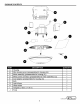
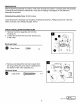
PACKAGE CONTENTS G PART A Housing B DESCRIPTION D E Wire housing cover (preassambled to housing (A)) Motor assembly (preassembled to housing (A)) Motor power connector (preassembled to motor assembly (C)) Duct adaptor (preassembled to housing (A)) F G H I Bulb Light kit pan Glass shade Template (7.56 in x 7.76 in) j Finial c QUANTITY 1 1 1 1 1 2 1 1 1 1 [m Lowes.com t:.
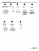
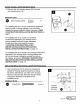
HARDWARE CONTENTS (shown actual size) • 9lllllDDDDl1llllllllll!D> • ~- ~ •B x3 Two-port Quick Connect (Preassembled to Product Wires) x4 Clip i ~ x8 Long Screw (Four screws are preassembled to Housing (A)) G) @)mill x2 x3 Motor Screw (Preassembled to Housing (A)) Mounting Bracket Nut (Preassem bled to Motor Assembly (C)) ~ B X1 Three-port Quick Connect (Preassembled to Product Wires) ~ X1 Wire Housing Screw (Preassem bled to Housing (A)) = \B x2 Washer Lowes .
A sAFETY INFORMATION READ AND SAVE THESE INSTRUCTIONS Please read and understand this entire manual before attempting to assemble, operate or install the product. AwARNING: Read all safety warnings and instructions. Failure to follow all warnings and instructions may result in electric shock, fire, and/or serious injury. Save all warnings and instructions for future use.
PREPARATION Before beginning assembly of product, make sure all parts are present. Compare parts with package contents list and hardware contents list. If any part is missing or damaged, do not attempt to assemble the product. Estimated Assembly Time: 30-60 minutes Tools Required for Assembly (not included): Flathead screwdriver, Phillips screwdriver, Hammer, Nails, Duct tape, Saw, Measuring tape, Pencil INITIAL INSTALLATION INSTRUCTIONS 1. Remove the motor assembly (C) from the housing (A). a.
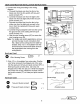
INITIAL INSTALLATION INSTRUCTIONS 3. Remove the wire housing screw (EE) from the wire housing cover (B). Hardware Used • Wire Housing Screw @)miD x 1 For installing the fan in a new construction application where drywall or ceiling material is not previously installed (exposed joists are visible), proceed to NEW CONSTRUCTION INSTALLATION INSTRUCTIONS on page 7.
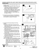
NEW CONSTRUCTION INSTALLATION INSTRUCTIONS 2. Connect the wiring according to the wiring diagram. a. Connect the black wire from the fan to the black wire from the fan switch with two-port quick connect (FF). b. Connect the black wire from the light to the black wire from the light switch with two-port quick connect (FF). c. Connect the white wire from the fan to the white wire from the light and connect to the line in from the ceiling with three-port quick connect (GG). d.
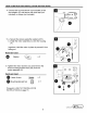
NEW CONSTRUCTION INSTALLATION INSTRUCTIONS 4. Connect the round ductwork (not included) to the duct adaptor (E) and secure with duct tape (not included) or clamps (not included). G 5. a. Secure the screws using the washers (HH). b. Install the motor assembly (C) into the housing (A). ll I Important: Hold the motor in place to prevent it from falling out. Hardware Used Washer x2 6. Tighten the motor screws (CC) and remove the three mounting bracket nuts (DD) from the motor assembly (C).
EXISTING CONSTRUCTION (JOIST/ ABOVE CEILING ACCESS APPLICATION) INSTALLATION INSTRUCTIONS 1. Perform one of the following steps based on the installation type: a. If there is an existing fan in place, remove the existing fan and ensure the opening in the ceiling is large enough for the new fan. b. If there is not an existing fan in place, choose the location in the ceiling and cut an opening according to the size of the template (I). Ensure one edge of the opening aligns with the edge of the joist. 2.
EXISTING CONSTRUCTION (JOIST/ ABOVE CEILING ACCESS APPLICATION) INSTALLATION INSTRUCTIONS 4. Strip 1/2 in. of insulation from wire ends. Grip the wire firmly and push the stripped end of the wire into the open port of two-port quick connect (FF) or three-port quick connect (GG). Use only one stripped end of the wire per port. Verify the stripped end of the wire is fully inserted to the back of twoport quick connect (FF) or three-port quick connect (GG).
EXISTING CONSTRUCTION (JOIST/ ABOVE CEILING ACCESS APPLICATION) INSTALLATION INSTRUCTIONS 6. Use long screws (AA) to screw the housing (A) directly to the joist using the keyhole mounting tab holes. Alternatively, one side of the housing has four holes and the other side has two holes. Choose the side that works best for the installation area. n-------CD~~_-_./:.:;::.: CD -------==--....o Hardware Used • Long Screw OllllllllDDDDDDIJIJl!j)> x 2 or 4 7. a. Secure the screws using the washers (H H). b.
EXISTING CONSTRUCTION (BELOW CEILING APPLICATION) INSTALLATION INSTRUCTIONS 1. Perform one of the following steps based on the installation type: a. lfthere is an existing fan in place, remove the existing fan and ensure the opening in the ceiling is large enough for the new fan. Use the template (I) provided to determine if the existing hole in the ceiling is large enough for this new fan to be installed. You may be required to make the hole larger to match the size of the template (I) provided.
EXISTING CONSTRUCTION (BELOW CEILING APPLICATION) INSTALLATION INSTRUCTIONS 3. Connect the wiring according to the wiring diagram. a. Connect the black wire from the fan to the black wire from the fan wall switch with twoport quick connect (FF). b. Connect the black wire from the light to the black wire from the light switch with two-port quick connect (FF). c. Connect the white wire from the fan to the white wire from the light and connect to the line in from the ceiling with three-port quick connect (GG).
EXISTING CONSTRUCTION (BELOW CEILING APPLICATION) INSTALLATION INSTRUCTIONS 5. Connect the round duckwork (not included) to the duct adaptor (E) and secure with duct tape (not included) or clamps (not included). 6. Place two clips (BB) along the bottom edge of each side of the housing (A). Place the housing (A) into the opening, then mount the housing (A) to the joist. Note: The clips (BB) will ensure the bottom edge of the housing (A) is flush with the ceiling board. Hardware Used Clip x4 7.
EXISTING CONSTRUCTION (BELOW CEILING APPLICATION) INSTALLATION INSTRUCTIONS 8. a. Secure the screws using the washers (HH). b. Install the motor assembly (C) into the housing (A). Important: Hold the motor in place to prevent it from falling out. 1~1 t Hardware Used Washer X 2 9. Tight the motor screws (CC) and remove the three mounting bracket nuts (DO) from the motor assembly (C).
LIGHT KIT INSTALLATION INSTRUCTIONS 2. Install three mounting bracket nuts (DO) on the threaded rods on the motor assembly (C) and tighten until the light kit pan (G) is flush with the finished ceiling. e Hardware Used ~ Mounting Bracket Nut 3 X 3. a. Install two bulbs (F) into the socket on the light kit pan (G). b. Place the glass shade (H) over the center threaded rod in the light kit pan (G). c. Tighten the finial (J).
CARE AND MAINTENANCE Cleaning the Fan Assembly 1. Switch the power off at the service panel and lock the service disconnecting means to prevent power from being switched on accidently. 2. Remove the light kit pan and unplug the fan assembly. 3. Gently vacuum the fan, motor and interior of the housing. TROUBLESHOOTING PROBLEM The fan does not turn on. POSSIBLE CAUSE 1. The fuse has blown or the breaker needs to be reset. 2. There is a loose connection in one or more of the wires. 3.
WARRANTY The manufacturer makes the following limited warranty to the original user or consumer purchaser of this bath fan: If any part of the bath fan (except for glass fixtures and light bulbs) fails at any time within one year after the date of sale to you due to a defect in material or workmanship, we will repair or, at our option, replace the defective part free of charge.
ARTICULO #0553454 .... UTILITECHlM VENTILADOR PARA BANO MODELO #00759 Grounded in Quality ... ADJUNTE AQUi SU RECIBO Numero de serie ----- Fecha de compra _ _ _ __ ~ LPreguntas, problemas, piezas faltantes?Antes de regresar al vendedor, llame a nuestro ~ departamento de servicio al ciente al 1-866-994-4148, de lunes a jueves de 8 a.m. a 6 p.m. (hora del este) y viernes de 8 a.m. a 5 p.m. (hora del este).
CONTENIDO Contenido del paquete Aditamentos 0 0 0 0 0 0 0 0 0 0 0 0 0 0 0 0 0 0 0 0 0 0 0 0 0 0 0 0 0 0 0 0 0 0 0 0 0 0 0 0 0 0 0 0 0 0 0 0 0 0 0 0 0 0 0 0 0 0 0 0 0 0 0 0 0 0 0 0 0 0 0 0 0 0 0 0 0 0 0 0 0 0 0 0 0 0 0 0 0 0 0 0 0 0 0 0 0 0 0 0 0 0 0 0 0 0 0 0 0 0 0 0 0 0 0 0 0 0 0 0 0 0 0 0 0 0 0 0 0 0 0 0 0 0 0 0 0 0 0 0 0 0 0 0 0 0 0 0 0 0 0 0 0 0 0 0
CONTENIDO DEL PAQUETE G PIEZA DESCRIPCION CANTIDAD A B Estruetura Cubierta de Ia estruetura de eableado (preaeoplada a Ia estruetura (A)) 1 1 c Motor (preaeoplado a Ia estruetura (A)) Coneetor de eorriente para el motor (preaeoplado al motor (C)) Adaptador para eondueto (preaeoplado a Ia estruetura (A)) Bombilla 1 1 1 2 Plaf6n del kit de luz Pantalla de vidrio Plantilla (19,20 em x 19,70 em) Remate 1 1 1 1 D E F G H I J Lowes .
ADITAMENTOS (se muestra el tamario real) • 911llllllllll11111111l)l))JID> • • ~ - @)mill G 0 i @mill 8 4 2 3 1 Tornillos largos Sujetadores Tornillos del motor (preacoplado a Ia estructura (A)) Tuercasdel soporte de montaje (preacoplados al soporte de montaje (C)) Tornillo para Ia estructura de cableado (preacoplado a Ia estructura (A)) (Hay Cuatro tornillos preensamblados en Ia carcasa (A).
INFORMACION DE SEGURIDAD LEA Y CONSERVE ESTAS INSTRUCCIONES Por favor, lea y comprenda este manual completamente antes de proceder a ensamblar, usar o instalar el producto. A A ADVERTENCIA: Lea todas las instrucciones y advertencias de seguridad. El incumplimiento de estas advertencias e instrucciones pudiera ocasionar descargas electricas, incendios y/o lesiones graves. Conserve todas las advertencias e instrucciones para su referencia futura.
PREPARACION Antes de comenzar el ensamblaje del producto, asegurese de tener todas las piezas. Compare las piezas con las listas de contenido del paquete y de aditamentos. Si hubiera piezas faltantes o danadas, no intente ensamblar el producto. Tiempo aproximado de instalaci6n: De 30 a 60 minutes Herramientas necesarias para el ensamblaje (nose incluyen): Destornillador plano, destornillador Phillips, martillo, clavos, cinta para conductos, sierra, cinta metrica INSTRUCCIONES PARA LA INSTALACION INICIAL 1.
INSTRUCCIONES PARA LA INSTALACION INICIAL 3. Retire el tornillo de Ia carcasa de los conductores (EE) de Ia cubierta de Ia carcasa de los conductores (B). Aditamento usado ~Tornillo de Ia estructura de X1 cableado Para instalar el ventilador en una aplicaci6n de construcci6n nueva donde nose haya instalado panel de yeso o material de techo (las viguetas son visibles), siga con Ia etapa INSTRUCCIONES DE INSTALACION PARA CONSTRUCCIONES NUEVAS en Ia pagina 26.
INSTRUCCIONES PARA LA INSTALACION EN CONSTRUCCIONES NUEVAS 2. Conecte los alambres de acuerdo con el diagrama de cableado. a. Conecte el conductor negro del ventilador al conductor negro del interrupter del ventilador con un conector de conexi6n rapida de dos puertos (FF). b. Conecte el conductor negro de Ia luz al conductor negro del interrupter de Ia luz con un conector de conexi6n rapida de dos puertos (FF). c.
INSTRUCCIONES PARA LA INSTALACION EN CONSTRUCCIONES NUEVAS 4. Conecte el conducto cilfndrico (nose incluye) al adaptador para conducto (E) y ffjelo con cinta para conductos (no se incluye) o abrazaderas (no se incluyen). G 5. a. Fije los tornillos con ayuda de las arandelas (HH). b. lnstale el ensamble del motor (C) en Ia carcasa (A). lmportante: Sostenga el motor en su Iugar para evitar que se caiga. Aditamento usado Arandelas X 2 6.
INSTRUCCIONES DE INSTALACION PARA CONSTRUCCIONES EXISTENTES (APLICACIONES CON ACCESO SOBRE EL TECHONIGUETAl 1. Real ice uno de los pasos siguientes segun el tipo de instalaci6n: a. Si hay un ventilador existente instalado, retfrelo y asegurese de que Ia abertura en el techo sea lo suficientemente grande para el ventilador nuevo. b. Si no hay un ventilador existente instalado, elija ellugar en el techo y corte una abertura del tamario de Ia plantilla (J).
INSTRUCCIONES DE INSTALACION PARA CONSTRUCCIONES EXISTENTES (APLICACIONES CON ACCESO SOBRE EL TECHONIGUETAl 4. Pele 1,27 em del aislamiento de los extremes de los conductores. Sujete firmemente el conductor y empuje el extrema pelado del conductor dentro del puerto abierto del conector de conexi6n rapida de dos puertos (FF) o de conector de conexi6n rapida de tres puertos (GG). Use solo un extrema pelado del conductor par puerto.
INSTRUCCIONES DE INSTALACION PARA CONSTRUCCIONES EXISTENTES (APLICACIONES CON ACCESO SOBRE EL TECHO/VIGUETAl 6. Use los tornillos largos (AA) para fijar Ia estructura (A) directamente a Ia viga usando los orificios tipo llave de las lenguetas de montaje. Como alternativa, un lade de Ia carcasa tiene cuatro orificios y el otro lade tiene dos orificios. Elija ellado que mejor se adecue al area de instalaci6n.
INSTRUCCIONES DE INSTALACION PARA CONSTRUCCIONES EXISTENTES (APLICACIONES CON ACCESO BAJO EL TECHO) 1. Real ice uno de los pasos siguientes segun el tipo de instalaci6n: a. Si hay un ventilador existente instalado, retfrelo y asegurese de que Ia abertura en el techo sea lo suficientemente grande para el ventilador nuevo.Use Ia plantilla (I) suministrada para determinar si el orificio existente en el techo es lo suficientemente grande para el ventilador nuevo que va a instalar.
INSTRUCCIONES DE INSTALACION PARA CONSTRUCCIONES EXISTENTES (APLICACIONES CON ACCESO BAJO EL TECHO) 3. Conecte los alambres de acuerdo con el diagrama de cableado. a. Conecte el conductor negro del ventilador al conductor negro del interrupter del ventilador con un conector de conexi6n rapida de dos puertos (FF). b. Conecte el conductor negro de Ia luz al conductor negro del interrupter de Ia luz con un conector de conexi6n rapida de dos puertos (FF). c.
INSTRUCCIONES DE INSTALACION PARA CONSTRUCCIONES EXISTENTES (APLICACIONES CON ACCESO BAJO EL TECHO) 5. Conecte el conducto cilfndrico (nose incluye) al adaptador para conducto (E) y ffjelo con cinta para conductos (nose incluye) o abrazaderas (no se incluyen). 6. Coloque dos sujetadores (BB) a lo largo del borde inferior de cada lade de Ia estructura (A). Coloque Ia estructura (A) en Ia abertura y fije luego Ia estructura (A) a Ia viga.
INSTRUCCIONES DE INSTALACION PARA CONSTRUCCIONES EXISTENTES (APLICACIONES CON ACCESO BAJO EL TECHO) 8. a. Fije los tornillos con ayuda de las arandelas (HH). b. lnstale el ensamble del motor (C) en Ia carcasa (A). lmportante: Sostenga el motor en su Iugar para evitar que se caiga. ll t Aditamento usado Arandelas X 2 9. Apriete los tornillos del motor (CC) y retire las tres tuercas de Ia abrazadera de montaje (DO) en el ensamble del motor (C).
INSTRUCCIONES DE INSTALACION DEL KIT DE ILUMINACION 2. lnstale tres dos tuercas (DD) del soporte de montaje en las varillas con rosca y apriete hasta que el plaf6n del kit de luz (G) quede a ras con el techo acabado. e Aditamento usado Tuercasdel soporte de montaje i X 3 3. a. lnstale dos bombillas (F) en el portalampara de Ia bandeja del kit de iluminaci6n (G). b. Coloque Ia pantalla de vidrio (H) sobre las varillas con rosca del plaf6n del kit de luz (G). c. Apriete el remate (J).
CUIDADO Y MANTENIMIENTO Limpieza del ventilador 1. Desconecte Ia electricidad en el panel de servicio y bloquee el acceso al mismo para evitar que alguien conecte Ia electricidad accidentalmente. 2. Retire el plaf6n del kit de luz y desenchufe el ventilador (toma negra). 3. Con una aspiradora, limpie suave mente el ventilador, el motor y el interior de Ia estructura. DETECCION DE PROBLEMAS PROBLEMA El ventilador no enciende. CAUSA POSIBLE 1.
GARANTiA El fabricante emite Ia siguiente garantfa limitada al usuario o comprador original de este ventilador de balio: Si cualquier pieza de este ventilador de balio (excepto las piezas de vidrio y las bombillas) tuviera fallos en algun momento durante el primer alio a partir de Ia fecha de compra debido a un defecto de materiales o de fabricaci6n, repararemos o reemplazaremos, a discreci6n nuestra, Ia pieza defectuosa sin costo alguno.
ARTICLE N° 0553454 VENTILATEUR DE SALLE DE BAIN UTILITECHlM Grounded in Quality'"' MODELE N° 00759 CD (]) JOIGNEZ VOTRE RECU ICI Numero de serie ® ---- Date d'achat _ _ __ Questions, problemes, pieces manquantes? Avant de retourner chez votre detaillant, appelez notre service a Ia clientele au 1 866 994 4148, 8 h a 18 h, HNE, du lundi au jeudi, et de 8 h a 17 h, HNE, le vendredi. Lowes.com ~ ~ LITILITECH.
TABLE DES MATII~RES Contenu de Ia bol'te ............................................................................................................... 41 Materiel ...............................................................................................................42 Renseignements sur Ia securite ......................................................................................... 43 Preparation .................................................................................................
CONTENU DE LA BOiTE G PIECE DESCRIPTION QUANTITE A B Boitier Couvercle du boitier de rangement des fils (preassemble au boltier [A]) Groupe moto-ventilateur (preassemble au boitier [A]) Connecteur d'alimentation du moteur (preassemble au groupe motoventilateur [C]) 1 1 c D E F G H I j 1 1 Adaptateur de conduit (preassemble au boitier [A]) Ampoule Plaque de !'ensemble d'eclairage Abat-jour en verre 1 2 1 1 Plaque (19,20 em x 19,70 em) Em bout 1 1 ~ UTILITECH. ) Lowes.
MATERIEL (illustre en taille reelle) • 9lllll)))})J)J)J)Jllll0Dlll> x8 Vis longues (Quatre vis sont pre asse mblees au boitier [A]) x3 Raccord a branchement rapide a deux orifices (preassem bles aux fils de !'article) ~- ~ e CD ~ i x2 Vis de moteur (preassemblees au baTtier [A]) x4 Attaches X1 Raccord branchement rapide trois orifices (preassembles aux fils de !'article) e @)miD x3 Ecrous de support de montage (preassemblees au groupe motaventilateur [C]) X1 Vis de boitier de rangement des fi
A RENSEIGNEMENTS SUR LA SECURITE VEUILLEZ LIRE ET CONSERVER CES INSTRUCTIONS V~illez lire et comprendre ce manuel en entier avant de tenter d'assembler, d'utiliser ou d'installer le produit. ~AVERTISSEMENT: Lire tous les avertissements de securite et toutes les instructions. Le non-respect des avertissements et des instructions peut entrainer un choc electrique, un incendie et/ou des blessures graves. Conservez tous les avertissements et les instructions pour une utilisation future.
PREPARATION Avant de commencer !'assemblage du produit, s'assurer que toutes les pieces sent incluses. Comparer les pieces avec Ia liste de materiel incluse dans l'emballage. Ne pas tenter d'assembler le produit si une piece est manquante ou endommagee. Temps d'installation estime: 30 a 60 minutes Outils requis pour !'assemblage (non inclus) : tournevis a tete plate, tournevis marteau, claus, ruban adhesif, scie, ruban a mesurer, crayon INSTRUCTIONS D'INSTALLATION INITIALE 1.
INSTRUCTIONS D'INSTALLATION INITIALE 3. Retirez Ia vis du boltier metallique (EE) du couvercle du boltier metallique (B). Materiel utilise Vis du boltier de rangement des fils X1 Lorsque vous installez le ventilateur dans le cadre d'une nouvelle construction ou Ia cloison seche ou le plafond n'a pas encore ete installe (les so lives sont visibles), passez a Ia section INSTRUCTIONS POUR L'INSTALLATION DANS LE CADRE D'UNE NOUVELLE CONSTRUCTION, a Ia page 45.
INSTRUCTIONS D'INSTALLATION SUR UN NOUVEL ELEMENT DE CONSTRUCTION 2. Connecter les fils selon le schema de cablage. a. Raccordez le fil noir du ventilateur au fil noir de l'interrupteur du ventilateur a l'aide d'un raccord a branchement rapide a deux orifices (FF). b. Raccordez le fil noir du luminaire au fil noir de l'interrupteur du luminaire a l'aide d'un raccord a branchement rapide a deux orifices (FF). c.
INSTRUCTIONS D'INSTALLATION SUR UN NOUVEL ELEMENT DE CONSTRUCTION 4. Raccorder le conduit rand (non inclus) a l'adaptateur de conduit (E) et le fixer avec du ruban adhesif en toile (non inclus) ou des attaches de serrage (non incluses). G 5. a. Serrez les vis a l'aide des rondelles (HH). b. Installer le groupe moto-ventilateur (B) dans le boitier (A). Important: Maintenir le groupe moto-ventilateur en place afin d'eviter qu'il ne ressorte. Materiel utilise Ronde lies x2 6.
INSTRUCTIONS POUR L'INSTALLATION DANS LE CADRE D'UNE CONSTRUCTION EXISTANTE (SOLIVE/INSTALLATION AU PLAFOND AVEC ACCES PARLE HAUT) 1. Effectuer l'une des etapes suivantes en fonction du type d'installation : a. Si un ventilateur est deja en place, le retirer et s'assurer que l'ouverture au plafond est suffisamment grande pour le nouveau ventilateur. b. S'il n'y a pas deja un ventilateur, choisir un emplacement au plafond et decouper une ouverture en fonction de Ia taille du modele (1).
INSTRUCTIONS POUR L'INSTALLATION DANS LE CADRE D'UNE CONSTRUCTION EXISTANTE (SOLIVE/INSTALLATION AU PLAFOND AVEC ACCES PARLE HAUT) 4. Denudez 12,7 mm de l'extremite des fils. Tenez fermement le filet poussez l'extremite denudee du fil dans !'orifice du raccord a branchement rapide a deux orifices (FF) ou du raccord a branchement rapide a trois orifices (GG). lnserez une seule extremite de fil denudee par orifice.
INSTRUCTIONS POUR L'INSTALLATION DANS LE CADRE D'UNE CONSTRUCTION EXISTANTE (SOLIVE/INSTALLATION AU PLAFOND AVEC ACCES PARLE HAUT) 6. Utiliser les vis longues (AA) pour visser directement le boltier a Ia poutre en utilisant les trous des pattes. Sachez que l'un des cotes du boltier est dote de quatre trous et que l'autre est dote de deux trous. Choisissez le cote le mieux adapte au lieu d'installation.
INSTRUCTIONS POUR L'INSTALLATION DANS LE CADRE D'UNE CONSTRUCTION EXISTANTE (INSTALLATION AU PLAFOND AVEC ACCES PARLE BAS) 1. Effectuer l'une des etapes suivantes en fonction du type d'installation: a. S'il y a deja un ventilateur, le retirer et s'assurer que l'ouverture au plafond est suffisamment grande pour le nouveau ventilateur. Utilisez le gabarit (I) fourni pour determiner si le trou deja present dans le plafond est assez large pour que vous puissiez y installer ce nouveau ventilateur.
INSTRUCTIONS POUR L'INSTALLATION DANS LE CADRE D'UNE CONSTRUCTION EXISTANTE (INSTALLATION AU PLAFOND AVEC ACCES PARLE BAS) 3. Connecter les fils selon le schema de cablage. a. Raccordez le fil noir du ventilateur au fil noir de l'interrupteur du ventilateur a l'aide d'un raccord a branchement rapide a deux orifices (FF). b. Raccordez le fil noir du lumina ire au fil noir de l'interrupteur du luminaire a l'aide d'un raccord a branchement rapide a deux orifices (FF). c.
INSTRUCTIONS POUR L'INSTALLATION DANS LE CADRE D'UNE CONSTRUCTION EXISTANTE (INSTALLATION AU PLAFOND AVEC ACCES PARLE BAS) a 5. Raccorder le conduit rand (non inclus) l'adaptateur de conduit (E) et le fixer avec du ruban adhesif en toile (non inclus) ou des attaches de serrage (non incluses). 6. Placer deux attaches (BB) le long du bard inferieur de chaque cote du boltier (A). Placer le boltier (A) dans l'ouverture, puis fixer le boltier (A) a Ia poutre.
INSTRUCTIONS POUR L'INSTALLATION DANS LE CADRE D'UNE CONSTRUCTION EXISTANTE (INSTALLATION AU PLAFOND AVEC ACCES PARLE BAS) 8. a. Serrez les vis a l'aide des ronde lies (HH). b. Installer le groupe moto-ventilateur (B) dans le boltier (A). 1~1 t Important: Maintenir le groupe moto-ventilateur en place afin d'eviter qu'il ne ressorte. Materiel utilise 4JD Rondelles X 2 9. Serrez les vis de moteur (CC), puis retirez les trois ecrous du support de fixation (DD) de !'ensemble de moteur (C).
INSTRUCTIONS POUR L'INSTALLATION DE L'ENSEMBLE D'ECLAIRAGE 2. Installer deux ecrous de support de montage (DO) sur les tiges filetees et serrer jusqu'a ce que Ia plaque de !'ensemble d'eclairage (G) soit a niveau avec le pia fond fini. Materiel utilise Ecrous de support de montage X 3 3. a. Vissez deux ampoules (F) dans les douilles situees sur Ia plaque de !'ensemble d'eclairage (G). b. Placez l'abat-jour en verre (H) sur Ia tige filetee centrale situee sur Ia plaque de !'ensemble d'eclairage (G) . c.
NETTOYAGE ET ENTRETIEN Nettoyer le ventilateur assemble 1. Couper !'alimentation a partir du panneau electrique et bloquer les dispositifs de debranchement pour eviter que !'alimentation ne soit retablie par accident 2. Retirer Ia plaque de !'ensemble d'eclairage et debrancher le ventilateur (receptacle nair). 3. Nettoyer delicatement le ventilateur, le moteur et l'interieur du boitier a l'aide d'un aspirateur. DEPANNAGE PROBLEME Le ventilateur ne s'allume pas. CAUSES POSSIBLES MESURES CORRECTIVES 1.
GARANTIE Le fabricant offre Ia garantie limitee suivante ventilateur de salle de bain: a l'utilisateur initial ou a l'acheteur d'origine de ce Si une piece de ce ventilateur de salle de bain (sauf les montages en verre et les ampoules) tom be en panne a tout moment a partir de Ia date d'achat en raison d'un defaut du materiel ou de fabrication, nous reparerons ou, a notre discretion, remplacerons Ia piece defectueuse gratuitement.