
Installation Guide


NEW
CONSTRUCTION INSTALLATION INSTRUCTIONS
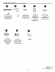
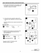
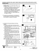
2. Connect the wiring according to the wiring
diagram.
a.
Connect the black wire from the fan to the
black wire from the fan switch with two-port
quick connect (FF).
b. Connect the black wire from the light to the
black wire from the light switch with two-port
quick connect (FF).
c.
Connect the white wire from the fan to the
white wire from the light and connect to the
line in from the ceiling with three-port quick
connect (GG).
d. Connect the ground/green wire from the unit to
the ground wire in the ceiling with two-port
quick connect (FF).
e.
Use the wire housing screw (EE) to screw the
wire housing
cover
(B).
Note: For single wall switch applications, remove
and cut the clear
2 port connectors from
the
2 black wires coming from the bath fan
chassis. Strip 1/2 in.
of
insulation from the
wire
ends
and connect both black wires to
the single black wire coming from the
ceiling/switch.
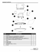
Hardware Used
• Wire Housing Screw
X 1
3. Strip 1/2 in.
of
insulation from wire ends. Grip the
wire firmly and push the stripped end
of
the wire
into the open port
of
two-port quick connect (FF)
or
three-port quick connect (GG). Use only one
stripped end
of
the wire per port. Verify the stripped
end
of
the wire is fully inserted to the back
of
two-
port quick connect (FF)
or
three-port quick connect
(GG).
Hardware Used
Two-port Quick connect B
Three-port Quick connect B
X 3
X 1
8
Switch Box
-Black
==-White
= Greenl(bare)
Fan
house
house
wires
~
~
UTILITECH' )
L
o
w
es
.
com
~
-·-
·