
Installation Guide


EXISTING CONSTRUCTION (BELOW CEILING APPLICATION) INSTALLATION INSTRUCTIONS
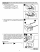
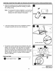
5. Place
two
clips (BB) along
the
bottom edge
of
each
side
of
the
housing
(A). Place
the
housing (A) into
the
opening,
then
mount
the
housing (A) to the joist.
Note: The clips (BB) will ensure the bottom edge
of
the
housing (A) is flush with
the
ceiling board.
Hardware Used
eclip
~
x4
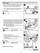
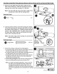
6. Use long
screws
(AA)
to
screw
the
housing (A) directly
to
the
joist
using keyhole mounting
tab
holes
or
holes on
the inside
of
the
housing (A).
Choose
the
side
that
best
works
for
the installation area. One side
of
the
housing
(A)
has
a foam insert. Remove and discard
this
foam
insert
when
choosing that side.
Note:
The
bottom
edge
of
the housing (A)
must
be flush
with
the
finished ceiling.
Hardware Used
• Long
Screw
Ol)))lll))l
ll\)1
)))))
I)))\)
0>
x 3
or
4
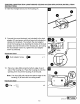
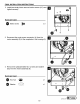
7.
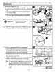
Connect the wiring according to the wiring diagram.
a. Connect the black wire from the fan to the black wire from
the fan switch with two-port quick connect (GG).
b.
Connect the black wire from the light to the black wire from
the light switch with two-port quick connect (GG).
c.
Connect the white wire from the fan to the white wire from
the light and connect to the line in from the ceiling with
three-port quick connect
(H
H).
d.
Connect the ground/green wire from the unit
to
the ground
wire
in
the ceiling with two-port quick connect (GG).
Note: For single wall switch applications, remove and cut
the clear 2 port connectors from the 2 black wires
coming from the bath fan chassis. Strip 1/2 in. of
insulation from the wire ends and connect both black
wires to the single black wire coming from the ceiling/
switch.
17
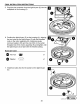
Sw
itch Box
- Black
=
\1\.trt
te
= Gr
ee
nl(b
are )
Fan
foam
~
UTILI
TECH'
]
Low
es
.
com
~
-·-: