ITEM #0553456 VENTILATION FAN UTILITECHlM MODEL #00762 Grounded in Quality"" Espanol p. 22 Fran9ais p. 43 ATTACH YOUR RECEIPT HERE Serial Number - - - - Purchase D a t e - - - - ~ Questions, problems, missing parts? Before returning to your retailer, call our customer ~service department at 1-866-994-4148, 8 a.m.- 6 p.m., EST, Monday- Thursday, 8 a.m.5 p.m., EST, Friday. ~ UTILITECH' ] -·-: AB13888 Lowes.
TABLE OF CONTENTS Package Contents .............................................................. 3 Hardware Contents ............................................................. 4 Safety Information .............................................................. 5 Preparation .................................................................... 6 Initial Installation Instructions ...................................................... 6 New Construction Installation Instructions ............................
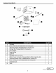
PACKAGE CONTENTS ·~ ~· <>--0 8----c:=t> PART DESCRIPTION QUANTITY A B Housing Motor Assembly (Preassembled to Housing (A)) c D E F Mounting Bracket (Preassembled to Housing (A)) Hanger Bar (Preassembled to Housing (A)) Duct Adaptor Light Kit Pan G H I J Light Kit Template (9.5 in. x 9.5 in.
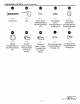
HARDWARE CONTENTS • ~shown actual sizel ~- 0 CD 9mmllnnnnnll rum11> ~ ~ om- x10 x4 x2 x2 x2 Long Screw Clip Motor Screw (Preassembled to Mounting Bracket (C)) Duct Adaptor Screw (Preassembled to Housing (A)) CD • Mounting Bracket Nut (Preassembled to Mounting Bracket (C)) •(Q) • ~ ~ G i • ®mm- @)mill x2 x4 X1 X1 x2 Washer (Preassembled to Mounting Bracket (C)) Two-port Quick Connect (Preassem bled to Product Wires) Three-port Quick Connect (Preasse m bled to Product Wir
A SAFETY INFORMATION READ AND SAVE THESE INSTRUCTIONS Please read and understand this entire manual before attempting to assemble, operate, or install the product. A WARNING: Read all safety warnings and all instructions. Failure to follow all warnings and instructions may result in electric shock, fire, and/or serious injury. Save all warnings and instructions for future use.
PREPARATION Before beginning assembly of the product, make sure all parts are present. Compare parts with the package contents list and hardware contents list. If any part is missing or damaged, do not attempt to assemble the product. Estimated Installation Time: 30 to 60 minutes Tools Required for Assembly (not included): Phillips screwdriver, Hammer, Nails, Duct tape, Saw, Measuring tape, Pencil, Ruler INITIAL INSTALLATION INSTRUCTIONS 1. Remove the motor assembly (B) and mounting bracket (C): a.
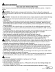
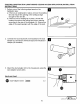
NEW CONSTRUCTION INSTALLATION INSTRUCTIONS 1. Use long screws (AA) to screw the housing (A) directly to the joist using keyhole mounting tab holes or the holes on the inside of the housing (A). One side of the housing (A) has four holes and keyhole mounting slots, the other side of the housing (A) has three holes. Choose the side that best works for the installation area. Note: The bottom edge of the housing (A) must be flush with the finished ceiling.
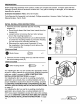
NEW CONSTRUCTION INSTALLATION INSTRUCTIONS 4. Insert the existing wires from the installation location through the punch-out hole on the housing (A). 5. Connect the wiring according to the wiring diagram. a. Connect the black wire from the fan to the black wire from the fan switch with two-port quick connect (GG). b. Connect the black wire from the light to the black wire from the light switch with two-port quick connect (GG). c.
NEW CONSTRUCTION INSTALLATION INSTRUCTIONS 7. Install the previously removed wire housing cover (K) into the housing (A) and secure using the wire housing screw (II). Ensure all of the wiring connections are inside of the housing (A) or under the wire housing cover (K). Hardware Used 0 Wire Housing Screw ~ X1 8. Connect the round ductwork (not included) to the duct adaptor (E) and secure with duct tape (not included) or clamps (not included). 9.
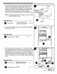
EXISTING CONSTRUCTION (JOIST/ABOVE CEILING ACCESS APPLICATION) INSTALLATION INSTRUCTIONS 1. Perform one of the following steps based on the installation type: a. lfthere is an existing fan in place, remove the existing fan and ensure the opening in the ceiling is large enough for the new fan. b. lfthere is not an existing fan in place, choose the location from above the ceiling and cut an opening according to the size of the template (H). Ensure one edge of the opening aligns with the edge of the joist.
EXISTING CONSTRUCTION (JOIST/ABOVE CEILING ACCESS APPLICATION) INSTALLATION INSTRUCTIONS 4. Place two clips (BB) along the bottom edge of each side of the housing (A). Place the housing (A) into the opening, then mount the housing (A) to the joist. Note: The clips (BB) will ensure the bottom edge of the housing (A) is flush with the ceiling board. Hardware Used QD Clip ~ x4 5.
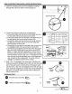
EXISTING CONSTRUCTION (JOIST/ABOVE CEILING ACCESS APPLICATION) INSTALLATION INSTRUCTIONS 7. Insert the existing wires from the installation location through the punch-out hole on the housing (A). punch-out hole 8. Connect the wiring according to the wiring diagram. a. Connect the black wire from the fan to the black wire from the fan switch with two-port quick connect (GG). b. Connect the black wire from the light to the black wire from the light switch with two-port quick connect (GG). c.
EXISTING CONSTRUCTION (JOIST/ABOVE CEILING ACCESS APPLICATION) INSTALLATION INSTRUCTIONS 10. Install the previously removed wire housing cover (K) into the housing (A) and secure using the wire housing screw (II). Ensure all of the wiring connections are inside of the housing (A) or under the wire housing cover (K). Hardware Used 0 Wire Housing Screw ~ X1 Proceed to FINAL INSTALLATION INSTRUCTIONS on page 16. EXISTING CONSTRUCTION (BELOW CEILING APPLICATION) INSTALLATION INSTRUCTIONS 1.
EXISTING CONSTRUCTION (BELOW CEILING APPLICATION) INSTALLATION INSTRUCTIONS 3. Insert the existing wires from the installation location through the punch-out hole on the housing (A). punch-out hole 4. Connect the round ductwork (not included) to the duct adaptor (E) and secure with duct tape (not included) or clamps (not included). 5. Attach the duct adaptor (E) to the housing (A) using the duct adaptor screws (DO). Hardware Used CD Duct Adaptor Screw ~ x2 Lowes .
EXISTING CONSTRUCTION (BELOW CEILING APPLICATION) INSTALLATION INSTRUCTIONS 6. Place two clips (BB) along the bottom of each side of the housing (A) to hold the housing (A) in place. Mount the housing (A) to the joist. Note: The clips (BB) will ensure the bottom edge of the housing (A) is flush with the ceiling board. Hardware Used eclip~ x4 7. Use long screws (AA) to screw the housing directly into the joist through the holes on either side of the housing (A).
EXISTING CONSTRUCTION (BELOW CEILING APPLICATION) INSTALLATION INSTRUCTIONS 9. Strip 1/2 in. of insulation from wire ends. Grip the wire firmly and push the stripped end of the wire into the open port of two-port quick connect (GG) or three-port quick connect (HH). Use only one stripped end of the wire per port. Verify the stripped end of the wire is fully inserted to the back of two-port quick connect (GG) or three-port quick connect (HH).
FINAL INSTALLATION INSTRUCTIONS 2. Insert the hook of the mounting bracket (C) into the slot on the housing (A). 3. Push the mounting bracket (C) up toward the housing (A) and align the two small hooks on the mounting bracket (C) into the slot on the housing (A). 4. Rotate the mounting bracket lock (J) clockwise to lock the mounting bracket (C) in place. Securely tighten the motor screws (CC), then remove the two mounting bracket nuts (EE) and washers (FF).
FINAL INSTALLATION INSTRUCTIONS 5. Reconnect the motor power connector (I) from the motor assembly (B) to the fan female receptacle in the housing (A). 6. Plug the wire connector from the light kit pan (F) into the light male receptacle in the housing (A). 7. Position the light kit pan (F) on the housing (A), aligning the two holes on the light kit pan (F) with the threaded rods on the mounting bracket (C).
FINAL INSTALLATION INSTRUCTIONS 8. Install one nightlight (L) and two bulbs (M) into the socket on the light kit pan (F). 0 • 9. Install the light kit (G) into the light kit pan (F) by putting the preassembled flange on the light kit (G) into the slide guide on the light kit pan (F). Important: Hold the light kit in place to prevent it from falling out. 0 t ~-----~.-~~ /_ 1 c ____O c CARE AND MAINTENANCE A WARNING: Never immerse metal or electrical parts in water.
CARE AND MAINTENANCE Cleaning the Fan Assembly 1. Switch the power off at the service panel and lock the service disconnecting means to prevent power from being switched on accidentally. 2. Remove the light kit pan and unplug the fan assembly. 3. Gently vacuum the fan, motor and interior of the housing. TROUBLESHOOTING PROBLEM The fan does not turn on. POSSIBLE CAUSE CORRECTIVE ACTION 1. The fuse has blown or the breaker needs to be reset. 2. There is a loose connection in one or more of the wires.
REPLACEMENT PARTS LIST For replacement parts, call our customer service department at 1-866-994-4148, 8 a.m.- 6 p.m., EST, Monday- Thursday, 8 a.m. - 5 p.m., EST, Friday. PART DESCRIPTION c E F Mounting Bracket Duct Adaptor Light Kit Pan G Light Kit PART# 107008-001 OMT 990599-0090BK 105000-0669BN 105000-067 4BN Printed in China Utilitech & UT Design® is a registered trademark of LF, LLC. All Rights Reserved. Low es .
ARTICULO #0553456 VENTILADOR UTILITECH™ MODELO #00762 Grounded in Qualitym ADJUNTE AQUi SU RECIBO Numero de serie _ _ __ Fecha de compra - - - - ~ l.Preguntas, problemas, piezas faltantes? Antes de regresar al vendedor, llame a ~ nuestro departamento de servicio al ciente al1-866-994-4148, de lunes a jueves de 8 a.m. a 6 p.m. (hera del este) y viernes de 8 a.m. a 5 p.m. (hera del este). Lowes .
CONTENIDO Contenido del paquete .......................................................... 24 Aditamentos .................................................................. 25 Informacion de seguridad ........................................................ 26 Preparaci6n .................................................................. 27 lnstrucciones para Ia instalaci6n inicial ............................................. 27 lnstrucciones para Ia instalaci6n en construcciones nuevas ...................
CONTENIDO DEL PAQUETE ·~ ~· <>--0 8----c:=t> PIEZA DESCRIPCION CANTIDAD A B Estruetura Motor (preaeoplado a Ia estruetura (A)) 1 1 c Soporte de montaje (preaeoplado a Ia estruetura (A)) Barra para eolgar (preaeoplado a Ia estruetura (A)) Adaptador para eondueto Plaf6n del kit de luees 1 4 1 1 j Kit de luees Plantilla (24,1 em x 24,1 em) Coneetor de eorriente para el motor (preaeoplado al motor (B)) Cierre del soporte de montaje (preaeoplado a Ia estruetura (A)) 1 1 1 1 K Cubierta de Ia estru
ADITAMENTOS • ~se 9mmllnnnnnl1rum11> 10 Tornillos largos muestra el tamario reaQ ~- 0 CD ~ ~ om- 4 Sujetadores •(Q) • ~ 2 Arandelas (preacopladas al soporte de montaje (C)) 4 Conector de conexi6n rapida de dos puertos (preensam blade a los conductores del producto) 2 Tornillos del motor (preacoplados al soporte de montaje (C)) CD ~ 1 Conector de conexi6n rapida de tres puertos (preensamblado a los conductores del producto) G i 2 2 Tornillos del Tuercasdel adaptador soporte de montaje par
INFORMACION DE SEGURIDAD LEA Y CONSERVE ESTAS INSTRUCCIONES Por favor, lea y comprenda este manual completamente antes de proceder a ensamblar, usar o instalar el producto. A A ADVERTENCIA: Lea todas las instrucciones y advertencias de seguridad. El incumplimiento de estas advertencias e instrucciones pudiera ocasionar descargas electricas, incendios y/o lesiones graves. Conserve todas las advertencias e instrucciones para su referencia futura.
PREPARATION Antes de comenzar el ensamblaje del producto, asegurese de tener todas las piezas. Compare las piezas con Ia lista del contenido del paquete y Ia lista de aditamentos. Si hubiera piezas faltantes o danadas, no intente ensamblar el producto. Tiempo aproximado de instalaci6n: De 30 a 60 minutos Herramientas necesarias para el ensamblaje (nose incluyen): Destornillador Phillips, martillo, clavos, cinta para conductos, sierra, cinta metrica, lapiz, regia.
INSTRUCCIONES PARA LA INSTALACION EN CONSTRUCCIONES NUEVAS 1. Use los tornillos largos (AA) para fijar Ia estructura (A) directamente a Ia viga usando los orificios tipo Ilave de las lenguetas de montaje o los orificios en el interior de Ia estructura (A). Uno de los Iadas de Ia estructura (A) tiene cuatro orificios y ranuras tipo llave, el otro lade de Ia estructura (A) tiene tres orificios. Elija el lade que mejor se adecue al area de instalaci6n.
INSTRUCCIONES PARA LA INSTALACION EN CONSTRUCCIONES NUEVAS 4. lnserte los alambres existentes del Iugar de instalaci6n a traves del orificio perforable de Ia estructura (A). 5. Conecte los alambres de acuerdo con el diagrama de cableado. a. Conecte el conductor negro del ventilador al conductor negro del interruptor del ventilador con un conector de conexi6n rapida de dos puertos (GG). b.
INSTRUCCIONES PARA LA INSTALACION EN CONSTRUCCIONES NUEVAS 7. lnstale Ia cubierta de Ia estructura de cableado (K) antes retirada en Ia estructura (A) y ffjela con el tornillo de Ia estructura de cableado (II). Asegurese de que todas las conexiones de alambres queden adentro de Ia estructura (A) o bajo Ia cubierta de Ia estructura de cableado (K). Aditamento usado X1 tornillo de Ia estructura de cableado 8.
INSTRUCCIONES DE INSTALACION PARA CONSTRUCCIONES EXISTENTES (APLICACIONES CON ACCESO SOBRE EL TECHONIGUETA) 1. Realice uno de los pasos siguientes segun el tipo de instalaci6n: a. Si hay un ventilador existente instalado, retfrelo y asegurese de que Ia abertura en el techo sea lo suficientemente grande para el ventilador nuevo. b. Si no hay un ventilador instalado, escoja Ia ubicaci6n desde encima del techo corte una abertura segun el tamario de Ia plantilla (H).
INSTRUCCIONES DE INSTALACION PARA CONSTRUCCIONES EXISTENTES (APLICACIONES CON ACCESO SOBRE EL TECHONIGUETA) 4. Coloque dos sujetadores (BB) a lo largo del borde inferior de cada lade de Ia estructura (A). Coloque Ia estructura (A) en Ia abertura y fije luego Ia estructura (A) a Ia viga. Nota: Los sujetadores (BB) garantizaran que el borde inferior de Ia estructura (A) quede a ras con el panel de techo. Aditamento usado IJ Sujetador ~ x4 5.
INSTRUCCIONES DE INSTALACION PARA CONSTRUCCIONES EXISTENTES (APLICACIONES CON ACCESO SOBRE EL TECHONIGUETA) 7. lnserte los alambres existentes del Iugar de instalaci6n a traves del orificio perforable de Ia estructura (A). orificio perforable 8. Conecte los alambres de acuerdo con el diagrama de cableado. a. Conecte el conductor negro del ventilador al conductor negro del interruptor del ventilador con un conector de conexi6n rapida de dos puertos (GG). b.
INSTRUCCIONES DE INSTALACION PARA CONSTRUCCIONES EXISTENTES (APLICACIONES CON ACCESO SOBRE EL TECHONIGUETA) 10. lnstale Ia cubierta de Ia estructura de cableado (K) antes retirada en Ia estructura (A) y ffjela con el tornillo de Ia estructura de cableado (II). Asegurese de que todas las conexiones de alambres queden adentro de Ia estructura (A) o bajo Ia cubierta de Ia estructura de cableado (K).
INSTRUCCIONES DE INSTALACION PARA CONSTRUCCIONES EXISTENTES (APLICACIONES CON ACCESO BAJO EL TECHO) 3. lnserte los alambres existentes del Iugar de instalaci6n a traves del orificio perforable de Ia estructura (A). 4. Conecte el conducto cilfndrico (nose incluye) al adaptador para conducto (E) y ffjelo con cinta para conductos (no se incluye) o abrazaderas (no se incluyen). 3. Acople el adaptador para conducto (E) a Ia estructura (A) usando los tornillos para el adaptador para conducto (DD).
INSTRUCCIONES DE INSTALACION PARA CONSTRUCCIONES EXISTENTES (APLICACIONES CON ACCESO BAJO EL TECHO) 6. Coloque dos sujetadores (BB) a lo largo del borde inferior de cada lado de Ia estructura (A) para montar Ia estructura (A) en su Iugar. Fije Ia estructura (A) a Ia viga. Nota: Los sujetadores (BB) garantizaran que el borde inferior de Ia estructura (A) quede a ras con el panel de techo. Aditamento usado ID Sujetadores ~ x4 orificios de las bocallaves de 7.
INSTRUCCIONES DE INSTALACION PARA CONSTRUCCIONES EXISTENTES (APLICACIONES CON ACCESO BAJO EL TECHO) 9. Pele 1,27 em del aislamiento de los extremes de los conductores. Sujete firmemente el conductor y empuje el extrema pelado del conductor dentro del puerto abierto del co nectar de conexi6n rapida de dos puertos (GG) o de conector de conexi6n rapida de tres puertos (HH). Use solo un extrema pelado del conductor par puerto.
INSTRUCCIONES PARA LA INSTALACION FINAL 2. lnserte el gancho del soporte de montaje (C) en Ia ranura de Ia estructura (A). 3. Empuje el soporte de montaje (C) hacia arriba, hacia Ia estructura (A) y alinee los dos ganchos pequerios del soporte de montaje (C) en Ia ranura de Ia estructura (A). 4. Rote el cierre del soporte de montaje (J) en el sentido del reloj para trabar el soporte de montaje (C) en su Iugar.
INSTRUCCIONES PARA LA INSTALACION FINAL 5. Vuelva a conectar el co nectar de alimentaci6n del motor (I) en el ensamble del motor (B) al receptacula hembra del ventilador en Ia carcasa (A). 6. Enchufe el conector del conductor en Ia bandeja del kit de iluminaci6n (F) en el receptacula macho de Ia luz en Ia carcasa (A). 7. Coloque el plaf6n del kit de luces (F) en Ia estructura (A) alineando los dos orificios del plaf6n del kit de luces (F) con las varillas con rosca del soporte de montaje (C).
INSTRUCCIONES PARA LA INSTALACION FINAL 8. lnstale una luz de noche (L) y dos bombillas (M) en el portalampara de Ia bandeja del kit de iluminaci6n (F). 0 • 9. lnstale el kit de iluminaci6n (G) en Ia bandeja del kit de iluminaci6n (F), para esto coloque Ia brida preensamblada en el kit de iluminaci6n (G) en Ia gula deslizable de Ia bandeja del kit de iluminaci6n (F). lmportante: Sostenga el kit de iluminaci6n en su Iugar para evitar que se caiga. 0 t ~-----~.
CUIDADO Y MANTENIMIENTO Limpieza del ventilador 1. Desconecte Ia electricidad en el panel de servicio y bloquee el acceso al mismo para evitar que alguien conecte Ia electricidad accidentalmente. 2. Retire el plaf6n del kit de luces y desenchufe el ventilador (toma negra). 3. Con una aspiradora, limpie suave mente el ventilador, el motor y el interior de Ia estructura. DETECCION DE PROBLEMAS PROBLEMA El ventilador no enciende. CAUSA POSIBLE SOLUCION 1.
LISTA DE PIEZAS DE REPU ESTO Para obtener piezas de repuesto, llame a nuestro departamento de servicio al cliente al 1-866-994-4148, de lunes a jueves de 8 a.m. a 6 p.m. (hora del este) y viernes de 8 a.m. a 5 p.m. (hora del este ). PIEZA DESCRIPCION #DE PIEZA c Soporte de montaje Adaptador para conducto 107008-001 OMT E F G Plaf6n del kit de luces Kit de luces 990599-0090BK 105000-0669BN 105000-067 4BN lmpreso en China Utilitech & UT Design® es una marca registrada de LF, LLC.
ARTICLE N° 0553456 VENTILATEUR UTILITECHlM MODELE N° 00762 Grounded in Quality"" JOIGNEZ VOTRE RECU ICI Numero de serie Date d'achat ~ Questions, problemes, pieces manquantes? Avant de retourner chez votre detaillant, ~ appelez notre service a Ia clientele au 1 866 994 4148, 8 h a 18 h, HNE, du lundi au jeudi, et de 8 h a 17 h, HNE, le vendredi. ~ UTILITECH' ] -·-: Lowes.
TABLE DES MATII~RES Contenu de Ia bol'te ............................................................ 49 Materiel ..................................................................... 50 Renseignements sur Ia securite ................................................... 51 Preparation ................................................................... 52 Instructions d'installation initiale ...................................................
CONTENU DE LA BOiTE ·~ ~· ~ 8----Ca PIECE DESCRIPTION QUANTITE A B Bol'tier Groupe moto-ventilateur (preassemble au baTtier [A]) 1 1 c Support de montage (preassemble au boitier [A]) Barre de montage (preassemble au boltier [A]) Adaptateur de conduit 1 4 1 Plaque de !'ensemble d'eclairage Ensemble d'eclairage 1 1 1 1 D E F G H I J K L M Plaque (24, 1 em x 24,1 em) Connecteur d'alimentation du moteur (preassemble au groupe motoventilateur [B]) Verrou du support de montage (preassemble au bo
MATERIEL Qllustre en taille reellel • ~- 0 CD 9mmllnnnnnl1rum11> ~ ~ om- x10 Vis longues x4 Attaches x2 Vis de moteur (preassemblees au support de montage [C]) x2 Vis d'adaptateur de conduit (pre asse mblees au boltier [A]) •(Q) • CD ~ x2 x4 Rondelles (preassemblees au support de montage [C]) Raccords branchement rapide deux orifices (preassembles aux fils de !'article) a a ~ X1 X1 a a i • ®a- Raccord branchement rapide trois orifices (preassemble aux fils de !'article) G x2 Ec
A RENSEIGNEMENTS SUR LA SECURITE VEUILLEZ LIRE ET CONSERVER CES INSTRUCTIONS Veuillez lire et comprendre ce manuel en entier avant de tenter d'assembler, d'utiliser ou d'installer le produit. A AVERTISSEMENT: Lire to us les avertissements de securite et toutes les instructions. Le non-respect des Ssements et des instructions peut entrainer un choc electrique, un incendie et'ou des blessures graves. Conservez tousles avertissements et les instructions pour une utilisation future.
PREPARATION Avant de commencer !'assemblage du produit, s'assurer que toutes les pieces sont incluses. Comparer les pieces avec Ia liste de materiel incluse dans l'emballage. Ne pas tenter d'assembler le produit si une piece est manquante ou endommagee. Temps d'installation estime: 30 a 60 minutes Outils requis pour !'assemblage (non inclus): tournevis adhesif, scie, ruban a mesurer, crayon, regie atete cruciforme, marteau, claus, ruban INSTRUCTIONS D'INSTALLATION INITIALE 1.
INSTRUCTIONS D'INSTALLATION SUR UN NOUVEL ELEMENT DE CONSTRUCTION 1. Utiliser les vis longues (AA) pour visser directement le boltier a Ia poutre en utilisant les trous des pattes de fixation ou les trous a l'interieur du boltier (A). L'un des cotes du boltier possede quatre trous et des fentes de montage, tandis que l'autre cote du boltier dispose de trois trous. Choisissez le cote le mieux adapte au lieu d 'installation. Remarque: Le bard inferieur du boltier (A) doit etre a niveau avec le plafond fini.
INSTRUCTIONS D'INSTALLATION SUR UN NOUVEL ELEMENT DE CONSTRUCTION 4. lnserer les fils existants provenant de !'emplacement d'installation dans le trou de depart perce sur le boTtier (A). trou perce 5. Connecter les fils selon le schema de cablage. a. Raccordez le fil noir du ventilateur au fil noir de l'interrupteur du ventilateur l'aide d'un raccord branchement rapide deux orifices (GG). b.
INSTRUCTIONS D'INSTALLATION SUR UN NOUVEL ELEMENT DE CONSTRUCTION 7. Installer le couvercle du baTtier derangement des fils prealablement enleve (K) sur le boltier (A) et le fixer a l'aide de Ia vis du boltier derangement des fils (II). S'assurer que toutes les connexions de fils se trouvent l'interieur du boltier (A) ou sous le couvercle du baTtier de rangement des fils (K). a Materiel utilise A W X1 Vis du boltier de rangement des fils 8.
INSTRUCTIONS POUR L'INSTALLATION DANS LE CADRE D'UNE CONSTRUCTION EXISTANTE (SOLIVE/INSTALLATION AU PLAFOND AVEC ACCES PARLE HAUT) 1. Effectuer l'une des etapes suivantes en fonction du type d'installation: a. Si un ventilateur est deja en place, le retirer et s'assurer que l'ouverture au plafond est suffisamment grande pour le nouveau ventilateur. b.
INSTRUCTIONS POUR L'INSTALLATION DANS LE CADRE D'UNE CONSTRUCTION EXISTANTE (SOLIVE/INSTALLATION AU PLAFOND AVEC ACCES PARLE HAUT) 4. Placer deux attaches (BB) le long du bord inferieur de chaque cote du boltier (A). Placer le boltier (A) dans l'ouverture, puis fixer le boltier (A) a Ia poutre. Remarque: Les attaches (BB) permettront de s'assurer que le bord inferieur du boltier (A) est a niveau avec le panneau-plafond. Materiel utilise ID ~ Attache x4 5.
INSTRUCTIONS POUR L'INSTALLATION DANS LE CADRE D'UNE CONSTRUCTION EXISTANTE (SOLIVE/INSTALLATION AU PLAFOND AVEC ACCES PARLE HAUT) 7. lnserer les fils existants provenant de !'emplacement d'installation dans le trou de depart perce sur le boltier (A). 8. Connecter les fils selon le schema de cablage. a. Raccordez le fil noir du ventilateur au fil noir de l'interrupteur du ventilateur a l'aide d'un raccord a branchement rapide a deux orifices (GG). b.
INSTRUCTIONS POUR L'INSTALLATION DANS LE CADRE D'UNE CONSTRUCTION EXISTANTE (SOLIVE/INSTALLATION AU PLAFOND AVEC ACCES PARLE HAUT) 10. Installer le couvercle du boltier de rangement des fils prealablement enleve (K) sur le boitier (A) et le fixer a l'aide de Ia vis du boitier de rangement des fils (II). S'assurer que toutes les connexions de fils se trouvent a l'interieur du boltier (A) ou sous le couvercle du boltier de rangement des fils (K).
INSTRUCTIONS POUR L'INSTALLATION DANS LE CADRE D'UNE CONSTRUCTION EXISTANTE (INSTALLATION AU PLAFOND AVEC ACCES PARLE BAS) 7. lnserer les fils existants provenant de !'emplacement d'installation dans le trou de depart perce sur le boltier (A). trou perce a 4. Raccorder le conduit rond (non inclus) l'adaptateur de conduit (E) et le fixer avec du ruban adhesif en toile (non inclus) ou des attaches de serrage (non incluses). 5.
INSTRUCTIONS POUR L'INSTALLATION DANS LE CADRE D'UNE CONSTRUCTION EXISTANTE (INSTALLATION AU PLAFOND AVEC ACCES PARLE BAS) 6. Place two clips (BB) along the bottom of each side of the housing (A) to hold the housing (A) in place. Mount the housing (A) to the joist. Note: The clips (BB) will ensure the bottom edge of the housing (A) is flush with the ceiling board. Hardware Used eclip~ x4 7.
INSTRUCTIONS POUR L'INSTALLATION DANS LE CADRE D'UNE CONSTRUCTION EXISTANTE (INSTALLATION AU PLAFOND AVEC ACCES PARLE BAS) 9. Denudez 12,7 mm de l'extremite des fils. Tenez fermement le filet poussez l'extremite denudee du fil dans !'orifice du raccord branchement rapide deux orifices (GG) ou du raccord branchement rapide trois orifices (HH). lnserez une seule extremite de fil denudee par orifice.
INSTRUCTIONS D'INSTALLATION FINALE 2. lnserer le crochet du support de montage (C) dans Ia fente sur le boitier (A). 3. Pousser le support de montage (C) vers le haut, vers le baTtier (A), et aligner les deux petits crochets sur le support de montage (C) dans Ia fente sur le boltier (A). 4. Tourner le verrou du support de montage (J) dans le sens horaire pour verrouiller le support de montage (C) et le maintenir en place.
INSTRUCTIONS D'INSTALLATION FINALE 5. Raccordez le connecteur d'alimentation du moteur (I) situe sur !'ensemble de moteur (B) a Ia prise femelle du ventilateur situee dans le baTtier (A). 6. lnserez le fil de Ia plaque de !'ensemble d'eclairage (F) dans !'orifice male du luminaire situe dans le baTtier (A). 7. Mettre en place Ia plaque de !'ensemble d'eclairage (F) sur le boltier (A), en alignant les deux trous de Ia plaque de !'ensemble d'eclairage (F) sur les tiges filetees du support de montage (C).
INSTRUCTIONS D'INSTALLATION FINALE 0 8. lnserez une veilleuse (L) et deux ampoules (M) dans les douilles de Ia plaque de !'ensemble d'eclairage (F). • • 9. lnstallez !'ensemble d'eclairage (G) sur Ia plaque de !'ensemble d'eclairage (F) en glissant les rebords preassembles !'ensemble d'eclairage (G) sur les glissieres de Ia plaque de !'ensemble d'eclairage (F). a Important: Tenez !'ensemble d'eclairage pour l'empecher de tomber.
NETTOYAGE ET ENTRETIEN Nettoyer le ventilateur assemble a 1. Couper !'alimentation partir du panneau electrique et bloquer les dispositifs de debranchement pour eviter que !'alimentation ne soit retablie par accident. 2. Retirer Ia plaque de !'ensemble d'eclairage et debrancher le ventilateur (receptacle noir). 3. Nettoyer delicatement le ventilateur, le moteur et l'interieur du boltier a l'aide d'un aspirateur. DEPANNAGE PROBLEME Le ventilateur ne s'allume pas. CAUSES POSSIBLES 1.
LISTE DES PIECES DE RECHANGE a Pour obtenir des pieces de rechange, appeler notre departement du service Ia clientele au 1 866 994 4148, de 8 h 18 h, H NE, du lundi au jeudi, et de 8 h 17 h, HNE, le vendredi. a PIECE c E F G a DESCRIPTION PIECE NO. 107008-001 OMT Support de montage Adaptateur de conduit 990599-0090BK Plaque de !'ensemble 105000-0669BN d'eclairage Ensemble d'eclairage 105000-067 4BN lmprime en Chine Utilitech & UT Design® est une marque deposee de LF, LLC. Taus droits reserves.