
Installation Guide


EXISTING CONSTRUCTION (JOIST/ABOVE CEILING ACCESS APPLICATION) INSTALLATION
INSTRUCTIONS
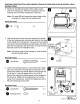
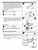
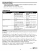
7. Insert the existing wires from the installation location
through the punch-out hole on the housing (A).
8. Connect the wiring according to the wiring diagram.
a. Connect the black wire from the fan to the black wire from
the fan switch with two-port quick connect (GG).
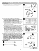
b.
Connect the black wire from the light to the black wire from
the light switch with two-port quick connect (GG).
c.
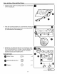
Connect the white wire from the fan
to
the white wire from
the light and connect to the line
in
from the ceiling with
three-port quick connect (HH).
d. Connect the the red wire from the light to the red wire from
the nightlight switch with two-port quick connect (GG).
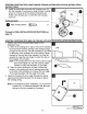
e. Connect the ground/green wire from the unit to the ground
bare wire
in
the ceiling with two-port quick connect (GG).
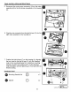
Note: For single wall switch applications, remove and cut
the clear 2 port connectors from the 2 black wires coming
from the bath fan chassis. Strip 1/2 in.
of
insulation from the
wire ends and connect both black wires
to
the single black
wire coming from the ceiling/switch.
To
use the red wire/
nightlight, an additional switch will be needed.
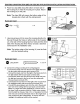
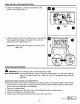
9.
Strip 1/2 in.
of
insulation from wire ends. Grip the wire
firmly and push the stripped end
of
the wire into the open
port
of
two-port quick connect (GG) or three-port quick
connect (HH). Use only one stripped end
of
the wire per
port. Verify the stripped end
of
the wire is fully inserted to
the back
of
two-port quick connect (GG) or three-port
quick connect (HH).
Hardware Used
G Two-port Quick Connect
f:b
x4
4JD
Three-port Quick
Connect~
X 1
12
punch-out hole
house
wires
120V
AC
Li
ne tn
~
UTILI
TECH'
J
Lowes .com
~
-·-