ITEM #0831384 TM HUMIDITY SENSING VENTILATION FAN MODEL #7131-02 Français p. 14 Español p. 27 ATTACH YOUR RECEIPT HERE Serial Number________________ Purchase Date_______________ Questions, problems, missing parts? Before returning to your retailer, call our customer service department at 1-866-994-4148, 8 a.m. - 6 p.m., EST, Monday - Thursday, 8 a.m. - 5 p.m., EST, Friday.
TABLE OF CONTENTS Product Specifications.........................................................................................................................2 Package Contents...............................................................................................................................3 Safety Information...............................................................................................................................4 Preparation..............................................
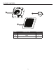
PACKAGE CONTENTS A C B PART A B C DESCRIPTION Fan housing Grille Duct connector 3 QUANTITY 1 1 1
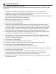
SAFETY INFORMATION READ AND SAVE THESE INSTRUCTIONS Please read and understand this entire manual before attempting to assemble, operate or install the product. 1. Always disconnect the power supply prior to servicing the fan, motor or junction box. 2. Installation work must be carried out by a qualified person(s) in accordance to all local and safety codes including the rules for fire-rated construction. 3.
PREPARATION Before beginning assembly of product, make sure all parts are present. Compare parts with package contents list and hardware contents. If any part is missing or damaged, do not attempt to assemble the product.
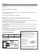
NEW CONSTRUCTION ASSEMBLY INSTRUCTIONS BEFORE INSTALLATION – Turn off power source. Review all safety precautions. 1 C 1. Attach the duct connector (C) to the fan housing (A). A 2. Remove wiring box cover (2.1) from fan housing (A). Remove wiring knockout (2.2) from wiring box cover with flathead screwdriver (not included). Attach the duct connector (C) to the fan housing (A). 2 2.2 A 2.1 2.2 2.3 3. Place the fan housing (A) next to a ceiling joist or wall stud.
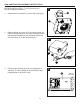
NEW CONSTRUCTION ASSEMBLY INSTRUCTIONS 4. Mount fan housing (A) to the joist or stud using wood screws (4.1) (not included) where indicated by arrows on fan housing (A). 4 4.1 A 5. Pull the house wires through the wire box cover hole. Using a quick connector, secure 120 V AC house wiring from the wall switch to the fan as shown in the wiring diagram on page 5. 14 AWG is the smallest conductor that should be used for branch-circuit wiring.
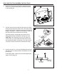
NEW CONSTRUCTION ASSEMBLY INSTRUCTIONS 7. Pinch mounting springs (7.1) on the grille (B) and insert into narrow rectangular slots (7.2) inside the fan housing (A). Push the grille (B) up toward ceiling. 7 7.2 8.3 A Turn on electricity at breaker box after finishing installation. 7.1 8.1 7.1 8.1 B 8.2 EXISTING CONSTRUCTION ASSEMBLY INSTRUCTIONS urn off electricity at breaker box before beginning T installation. Remove old fan. 1 C 1. Attach the duct connector (C) to the fan housing (A).
EXISTING CONSTRUCTION ASSEMBLY INSTRUCTIONS 3. Remove wiring box cover (3.1) from fan housing (A). Remove wiring knockout (3.2) from wiring box cover with flathead screwdriver (not included). 3 2.2 A 3.1 2.1 2.3 3.2 4. Pull the house wires through the wire box cover hole. Using a quick connector, secure 120 V AC house wiring from the wall switch to the fan as shown in the wiring diagram on page 5. 14 AWG is the smallest conductor that should be used for branch-circuit wiring.
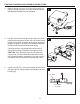
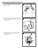
EXISTING CONSTRUCTION ASSEMBLY INSTRUCTIONS 6. Insert fan housing (A) through existing hole in ceiling. The fan housing (A) should be level and perpendicular to the joist or stud. 7. Mount fan housing (A) to the joist or stud using wood screws (7.1) (not included) where indicated by arrows on fan housing (A). 6 A 7 Joist or wall stud 7.1 8. Plug back in the power unit (8.1). Replace motor assembly (8.2) using the three screws (8.3) removed in step 1. 8 7. 1 8.1 8.2 7.2 7.3 8.
EXISTING CONSTRUCTION ASSEMBLY INSTRUCTIONS 9. Pinch mounting springs (9.1) on grille (B) and insert into narrow rectangular slots (9.2) inside the fan (A). Push grille (B) up toward ceiling. 9 9.2 8.3 Turn on electricity at breaker box after finishing installation. A 9.1 8.1 9.1 8.1 B 8.2 HUMIDITY SENSING OPERATION 1. umidity Sensing Mode: H Flip the wall on/off switch to the “ON” position. The LED indicator light in the fan is BLUE.
HUMIDITY SENSING OPERATION 3. Fan Off: Move the wall on/off switch to the “OFF” position. 3 CARE AND MAINTENANCE WARNING: Disconnect power supply before servicing. See SAFETY INFORMATION before proceeding. Routine maintenance should be done at least once a year. • Wash grille with mild soap and water, dry with a cloth. • Remove excess dirt and dust from the fan housing with a vacuum cleaner. • Do not use solvents, thinner or harsh chemicals for cleaning the fan.
TROUBLESHOOTING Sensor tolerance is +/- 10% The fan keeps running even though the house humidity level is lower than 60% RH. Built-in 10 minute delay time after humidity level is lower than 60% RH. Outdoor humidity is back drafting into the fan. Operating this fan requires minimal electricty so feel free to run the unit for continuous ventilation in your home. Turn the fan off when not in use.
ARTICLE #0831384 TM VENTILATEUR À CAPTEUR D’HUMIDITÉ MODÈLE #7131-02 JOIGNEZ VOTRE REÇU ICI Numéro de série______________ Date d’achat_________________ Des questions, des problèmes, des pièces manquantes? Avant de retourner l’article au détaillant, appelez notre service à la clientèle au 1 866 994-4148, entre 8 h et 18 h (HNE) du lundi au jeudi, ou entre 8 h et 17 h (HNE) le vendredi.
TABLE DES MATIÈRES Caractéristiques du produit...............................................................................................................15 Contenu de l’emballage et quincaillerie incluse................................................................................16 Consignes de sécurité.......................................................................................................................17 Préparation....................................................................
CONTENU DE L’EMBALLAGE A C B PIÈCE A B C DESCRIPTION Boîtier du ventilateur Grille Raccord pour conduit 16 QUANTITÉ 1 1 1
CONSIGNES DE SÉCURITÉ VEUILLEZ LIRE ET CONSERVER CES INSTRUCTIONS. Assurez-vous de lire et de comprendre l’intégralité du présent manuel avant de tenter d’assembler, d’installer ou d’utiliser l’article. 1. 2. 3. 4. 5. 6. 7. 8. 9. 10. 11. 12. 13. 14. 15. 16. 17. 18. Fermez toujours l’alimentation électrique avant d’effectuer l’entretien du ventilateur, du moteur ou de la boîte de jonction.
PRÉPARATION Avant de commencer l’assemblage du produit, assurez-vous d’avoir toutes les pièces. Comparez le contenu de l’emballage avec la liste des pièces et celle de la quincaillerie incluse. S’il y a des pièces manquantes ou endommagées, ne tentez pas d’assembler l’article. Temps d’assemblage approximatif : 30 minutes. Outils nécessaires pour l’assemblage (non inclus) : marteau, tournevis à tête plate, vis à bois, clous, ruban à conduits, tournevis cruciforme et couteau à lame rétractable.
INSTRUCTIONS POUR L’ASSEMBLAGE DANS UNE NOUVELLE CONSTRUCTION AVANT L’INSTALLATION : Coupez l’alimentation électrique. Consultez toutes les mesures de sécurité. 1 C 1. Fixez le raccord pour conduit (C) au boîtier du ventilateur (A). A 2. Retirez le couvercle de la boîte de câblage (2.1) du boîtier du ventilateur (A). Retirez la pastille défonçable (2.2) du couvercle de la boîte de câblage à l’aide d’un tournevis à tête plate (non inclus).
INSTRUCTIONS POUR L’ASSEMBLAGE DANS UNE NOUVELLE CONSTRUCTION 4. Fixez le boîtier de ventilateur (A) à la solive ou au montant en insérant des vis à bois (4.1) (non incluses) aux endroits indiqués par des flèches sur le boîtier du ventilateur (A). 4 4.1 A 5. Passez les fils de la maison à travers le trou du couvercle de la boîte de fils. À l’aide d’un raccord à branchement rapide, fixez le câblage de 120 V c.a.
INSTRUCTIONS POUR L’ASSEMBLAGE DANS UNE NOUVELLE CONSTRUCTION 7. Pincez les ressorts de fixation (7.1) sur la grille (B) et insérez-les dans les étroites fentes rectangulaires (7.2) à l’intérieur du boîtier du ventilateur (A). Poussez la grille (B) contre le plafond. 7 7.2 8.3 Après avoir terminé l’installation, rétablissez l’alimentation électrique à partir du panneau de disjoncteurs. A 7.1 8.1 7.1 8.1 B 8.
INSTRUCTIONS POUR L’ASSEMBLAGE DANS UNE CONSTRUCTION EXISTANTE 3. Retirez le couvercle de la boîte de câblage (3.1) du boîtier du ventilateur (A). Retirez la pastille défonçable (3.2) du couvercle de la boîte de câblage à l’aide d’un tournevis à tête plate (non inclus). 3 2.2 A 3.1 2.1 2.3 3.2 4. Passez les fils de la maison à travers le trou du couvercle de la boîte de fils. À l’aide d’un raccord à branchement rapide, fixez le câblage de 120 V c.a.
INSTRUCTIONS POUR L’ASSEMBLAGE DANS UNE CONSTRUCTION EXISTANTE 6. IInsérez le boîtier du ventilateur (A) dans le trou qui se trouve déjà au plafond. Le boîtier du ventilateur (A) doit être de niveau et perpendiculaire à la solive ou au montant. 6 7. Installez le boîtier de ventilateur (A) sur la solive ou le montant en utilisant des vis à bois (7.1) (non incluses) aux endroits indiqués par des flèches à l’intérieur du boîtier du ventilateur (A). 7 A Solive ou au montant 7.1 8.
INSTRUCTIONS POUR L’ASSEMBLAGE DANS UNE CONSTRUCTION EXISTANTE 9. Pincez les ressorts de fixation (9.1) sur la grille (B) et insérez-les dans les étroites fentes rectangulares (9.2) à l’intérieur du boîtier du ventilateur (A). Poussez la grille (B) contre le plafond. 9 9.2 8.3 A Après avoir terminé l’installation, rétablissez l’alimentation électrique à partir du panneau de disjoncteurs. 9.1 8.1 9.1 8.1 B 8.2 FONCTIONNEMENT DU CAPTEUR D’HUMIDITÉ 1.
FONCTIONNEMENT DU CAPTEUR D’HUMIDITÉ 3. Arrêt du ventilateur : Mettez l’interrupteur mural à la position « OFF » (arrêt). 3 ENTRETIEN AVERTISSEMENT : Coupez l’alimentation électrique avant d’effectuer l’entretien. Lisez les CONSIGNES DE SÉCURITÉ avant de commencer. Vous devez procéder à un entretien au moins une fois par année. • Nettoyez la grille à l’aide de savon doux et d’eau, et essuyez-la avec un linge. • Enlevez la poussière et la saleté du boîtier du ventilateur à l’aide d’un aspirateur.
DÉPANNAGE PROBLÈME CAUSE POSSIBLE MESURE CORRECTIVE La circulation d’air est insuffisante dans la pièce. Assurez-vous d’entrouvrir ou d’ouvrir complètement une porte ou une fenêtre pour permettre la circulation de l’air. Sans une circulation d’air adéquate, le ventilateur ne peut pas évacuer l’air de la pièce. Le débit en m³/min est insuffisant. Assurez-vous que le débit en m³/min du ventilateur correspond à celui exigé pour la taille de la pièce.
ARTÍCULO #0831384 TM VENTILADOR CON SENSOR DE HUMEDAD MODELO #7131-02 ADJUNTE SU RECIBO AQUÍ Número de serie______________ Fecha de compra_____________ ¿Preguntas, problemas, piezas faltantes? Antes de volver a la tienda, llame a nuestro Departamento de Servicio al Cliente al 1-866-994-4148, de lunes a jueves de 8 a.m. a 6 p.m., y los viernes de 8 a.m. a 5 p.m., hora estándar del Este.
ÍNDICE Especificaciones del producto.............................................................................................................2 Contenido del paquete........................................................................................................................3 Información de seguridad....................................................................................................................4 Preparación.....................................................................
CONTENIDO DEL PAQUETE A C B PIEZA A B C DESCRIPCIÓN Cuerpo del ventilador Rejilla Conector del conducto 29 CANTIDAD 1 1 1
INFORMACIÓN DE SEGURIDAD Lea y comprenda completamente este manual antes de intentar ensamblar, usar o instalar el producto. 1. 2. 3. 4. 5. 6. 7. 8. 9. 10. 11. 12. 13. 14. 15. 16. 17. 18. Desconecte siempre el suministro de electricidad antes de realizar tareas de mantenimiento en el ventilador, el motor o la caja de unión.
PREPARACIÓN Antes de comenzar a ensamblar el producto, asegúrese de tener todas las piezas. Compare las piezas con la lista del contenido del paquete y la lista de aditamentos. No intente ensamblar el producto si falta alguna pieza o si estas están dañadas.
INSTRUCCIONES DE ENSAMBLAJE PARA UNA CONSTRUCCIÓN NUEVA ANTES DE LA INSTALACIÓN – Apague la fuente de alimentación eléctrica. Revise todas las precauciones de seguridad. Retire el ventilador existente. 1 C 1. Adjunte el conector de conducto (C) a la carcasa del ventilador (A). A 2. Retire la cubierta de la caja del cableado (2.1) de la carcasa del ventilador (A). Retire el orificio ciego del cableado (2.2) de la cubierta de la caja del cableado con un destornillador de cabeza plana (no incluido).
INSTRUCCIONES DE ENSAMBLAJE PARA UNA CONSTRUCCIÓN NUEVA 4. Monte la carcasa del ventilador (A) en la vigueta o viga utilizando tornillos para madera (4.1) (no se incluyen), donde indican las flechas en la carcasa del ventilador (A). 4 4.1 A 5. Pase los conductores de la casa a través del orificio de la cubierta de la caja del cable.
INSTRUCCIONES DE ENSAMBLAJE PARA UNA CONSTRUCCIÓN NUEVA 7. Apriete los resortes de montaje (7.1) en la rejilla (7.2) e inserte en las ranuras rectangulares estrechas al interior del ventilador (A). Presione la rejilla (7.2) hacia el techo. 7 7.2 8.3 Conecte la electricidad en la caja del interruptor después de finalizar la instalación. A 7.1 8.1 7.1 8.1 B 8.
INSTRUCCIONES DE ENSAMBLAJE PARA UNA CONSTRUCCIÓN EXISTENTE 3. Retire la cubierta de la caja del cableado (3.1) de la carcasa del ventilador (A). Retire el orificio ciego del cableado (3.2) de la cubierta de la caja del cableado con un destornillador de cabeza plana (no incluido). 3 2.2 A 3.1 2.1 2.3 3.2 4. Pase los conductores de la casa a través del orificio de la cubierta de la caja del cable.
INSTRUCCIONES DE ENSAMBLAJE PARA UNA CONSTRUCCIÓN EXISTENTE 6. Inserte la carcasa del ventilador (A) a través del orificio existente en el techo. La carcasa del ventilador (A) debe estar al nivel de la vigueta o del montante y ser perpendicular a estos. 6 7. Monte la carcasa del ventilador en la vigueta o montante clavando donde indican las flechas al interior de la carcasa del ventilador (7.1). 7 A Vigueta o techo pared 7.1 8. Enchufe nuevamente en la unidad de tomacorriente (8.1).
INSTRUCCIONES DE ENSAMBLAJE PARA UNA CONSTRUCCIÓN EXISTENTE 9. Apriete los resortes de montaje (9.1) en la rejilla (9.2) e inserte en las ranuras rectangulares estrechas al interior del ventilador (A). Presione la rejilla (9.2) hacia el techo. 9 9.2 8.3 Conecte la electricidad en la caja del interruptor después de finalizar la instalación. A 9.1 8.1 9.1 8.1 B 8.2 FUNCIONAMIENTO DEL SENSOR DE HUMEDAD 1.
FUNCIONAMIENTO DEL SENSOR DE HUMEDAD 3. Ventilador apagado: Mueva el interruptor de encendido y apagado en la pared a la posición “OFF”. 3 CUIDADO Y MANTENIMIENTO ADVERTENCIA: Desconecte el suministro de electricidad antes de realizar tareas de mantenimiento. Vea la INFORMACIÓN DE SEGURIDAD antes de proceder. Se debe realizar mantenimiento de rutina al menos una vez al año. • Lave la rejilla con agua y jabón suave, y seque con un paño.
SOLUCIÓN DE PROBLEMAS El ventilador no ventila la habitación El ventilador no ventila la habitación El nivel de m3/min. es insuficiente La tolerancia del sensor es +/- 10% El ventilador sigue funcionando aunque el nivel de humedad de la casa sea inferior al 60% de humedad relativa. Tiempo de retraso de 10 minutos incorporado después de que el nivel de humedad sea inferior al 60% de humedad relativa. Hay corriente de aire de humedad exterior en el ventilador.