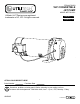
ITEM #0752650 1HP CONVERTIBLE JET PUMP ® MODEL #EFCWJ10-L Utilitech & UT Design® are registered trademarks of LF, LLC. All rights reserved. Français p. 16 Español p. 31 ATTACH YOUR RECEIPT HERE Serial Number Purchase Date Questions, problems, missing parts? Before returning to your retailer, call our customer service department 1-866-994-4148, 8 a.m. - 8 p.m., EST, Monday - Friday. AB15905 1 Lowes.
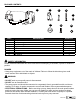
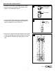
PACKAGE CONTENTS A B C D E F PART A B C D E F G H Pump Ejector Short Venturi Tube Long Venturi Tube Nozzle Gasket Bolt Flat Washer DESCRIPTION G H QUANTITY 1 1 1 1 1 1 2 2 SAFETY INFORMATION Please read and understand this entire manual before attempting to assemble, operate or install the product. DANGER • Keep pump equipment out of the reach of children! Failure to follow the directions given could cause serious risk to individuals or objects.
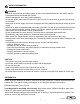
SAFETY INFORMATION WARNING • Follow all local electrical and safety codes, as well as the National Electrical Code (NEC) and the Occupational Safety and Health Act (OSHA). • Replace damaged or worn wiring cord immediately. • Do not kink power cable and never allow the cable to come in contact with oil, grease, hot surfaces, or chemicals. • Wire motor to correct supply. See motor nameplate and wiring diagrams and check voltage of power supply. • Unit must be securely and adequately electrically grounded.
PREPARATION Parts Required for Shallow Well Assembly (not included): PVC cement, thread tape, 1-1/4 in. foot valve, (2) 1-1/4 in. male PVC adapters, rigid 1-1/4 in. PVC pipe and couplings, well seal with vent plug, 1-1/4 in. PVC elbow, 1 in. discharge tee, pressure gauge, 1 in. male PVC adapter, 1 in. female PVC adapter, rigid 1 in. PVC pipe, 1 in. tank cross, (2) 1/4 in. plugs, 1/2 in. drain valve, 10 in. x 1 in. nipple.
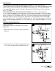
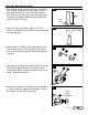
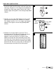
SHALLOW WELL INSTALLATION 1. Thread 1-1/4 in. male PVC adapter (not included) into foot valve (not included). Hand tighten, then tighten 1/4 turn with pipe wrench. 1 1-1/4 in. Male PVC Adapter Foot Valve 2. Using a 2-step PVC system (not included), attach enough PVC pipe and couplings to the adapter to equal the depth of the well, minus 5 ft. 2 3.
SHALLOW WELL INSTALLATION 4. Remove pipe clamp and slide well seal (not included) over rigid PVC pipe and onto well casing. Position assembly so that 12 in. of rigid PVC pipe protrude from well seal. Using wrench, turn bolts on well seal clockwise until rubber gaskets are tight against well casing and rigid PVC pipe. 4 5. Using a 2-step PVC system, attach a 1 in. PVC elbow (not included) onto the rigid PVC pipe extending from the well seal. 5 6. Open ejector kit.
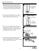
SHALLOW WELL INSTALLATION 9. Using 2-step PVC system, attach 1-1/4 in. PVC pipe and couplings (not included) as needed to connect the 1-1/4 in. male PVC adapter to the 1-1/4 in. PVC elbow attached to the top of the well pipe in step 5. NOTE: The horizontal pipe should be level or trending up toward the pump. 10. Wrap thread tape around the male threads on the discharge tee (not included). Using a pipe wrench, thread 1 in. discharge tee into top of pump (A).
SHALLOW WELL INSTALLATION 13. Thread 10 in. x 1 in. nipple into pressure tank (both not included). Thread tank cross into nipple so that the two 1/4 in. holes in tank cross face upward. Plug two outlets on tank cross with two 1/4 in. plugs. 13 1/4 in. Plugs Tank Cross Nipple 14. Thread 1/2 in. boiler drain into front of tank cross. Thread 1 in. male PVC adapter into inlet side of tank cross. Connect to household plumbing. 14 1/2 in. Boiler Drain 1 in. Male PVC Adapter 15.
DEEP WELL INSTALLATION 2. The ejector (B) has two holes in the top of it. Thread deep well venturi tube (D) (longer tube) into larger hole until snug. Thread 1 in. x 5 in. nipple (not included) into smaller hole. Only hand tighten venturi tube. Hand tighten nipple, then tighten 1/4 turn with pipe/adjustable wrench. 2 3. Thread a 1-1/4 in. male PVC adapter over the venturi tube (D) and into ejector (B). Thread a 1 in. female PVC adapter onto the 1 in. x 5 in. nipple.
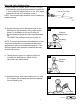
DEEP WELL INSTALLATION 5. Remove pipe clamp and slide well seal over PVC pipes and onto well casing. DO NOT let assembly slide down into well. Position assembly so that 12 in. of PVC pipes protrude from well seal. Using wrench, turn bolts on well seal clockwise until rubber gaskets are tight against the well casing and the PVC pipes. 5 12 in. of PVC Pipe Protruding From Well Seal Well Seal 6. Cut 1 in. pipe 2 in. shorter than the 1-1/4 in. pipe. Smooth rough edges. Cement 1 in. and 1-1/4 in.
DEEP WELL INSTALLATION 9. Open pressure regulator kit. Apply 2-3 wraps of thread tape to the male threads on the body of the pressure regulator. With pipe wrench, thread the pressure regulator into 1 in. discharge at top of pump (A). Use a pressure gauge with 1/8 in. NPT thread and thread pressure gauge into side of pump case. 9 Pressure Regulator A 10 10. Thread plug into opening to right of pressure regulator outlet. Pressure Regulator Outlet Plug 11 11. Thread 3/4 in.
DEEP WELL INSTALLATION 13. Thread boiler drain into front of tank tee. Thread 3/4 in. male PVC adapter into inlet side of tank tee. Connect to household plumbing. 13 3/4 in. Male PVC Adapter 1/2 in. Boiler Drain PUMP ELECTRICAL CONNECTIONS WARNING • Always disconnect pump from electricity before performing any work on the pump. • Under-sized wiring can cause motor failure and even fire. Use proper wire size specified in the Wire Size Chart.
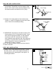
PUMP ELECTRICAL CONNECTIONS Wiring Pressure Switch Remove pressure switch cover and follow wiring directions on inside of cover. Be sure to ground wire the pressure switch to the motor. To Motor Ground Connections From Line PUMP PRIMING 1. Remove plug or pressure gauge at the top of the pump case. Fill suction pipe and pump with water until the water overflows from the top of pump case. Install plug loosely into pump case. Turn the pump on.
TROUBLESHOOTING PROBLEM Little or no discharge POSSIBLE CAUSE CORRECTIVE ACTION 1. Pump is not primed. 2. Suction lift too high or too long. 3. Hole or air leak in suction line. Pump will not deliver water or develop pressure Pump vibrates and/ or makes excessive noise Pump will not start or run 1. Follow priming instructions. 2. Move pump closer to water source. Lift should be less than 25 ft. for shallow well installations and less than 90 ft. for deep well installations. 3. Repair or replace.
WARRANTY LIMITED WARRANTY This pump is warranted to be free from defects in material and workmanship and to perform within applicable specifcations for a period of one (1) year. Obligation under this warranty is limited to repairing or replacing any part thereof, which shall within one year be returned to us with transportation charges prepaid, and proved to be defective.