
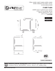
Use and Care Guide


7
PRESSURE
RELIEF VALVE
1/2 in. BOILER
DRAIN
Figure 3: Step 4
The complete installation should look like the drawing
shown below. See Figure 4.
PRESSURE
GAUGE
PRESSURE
SWITCH
OPTIONAL
GATE VALVE
TO
WELL
MALE PVC
ADAPTER
PRESSURE
RELIEF VALVE/
BOILER DRAIN/
STREET TEE
1/4 in. PLUG
TO
SYSTEM
VALVE
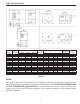
BASE MOUNTED JET PUMP WITH VERTICAL TANK
Figure 4
TYPICAL SUBMERSIBLE PUMP INSTALLATION
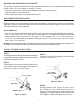
STEP 1
Thread10in.X1in.nippleintopressuretank.Thread
tank cross into nipple so that the two 1/4 in. holes in
tank cross face upward. Thread street tee into front
of tank cross. Thread pressure relief valve into top
of street tee and thread 3/4 in. boiler drain into front
of street tee.
TANK CROSS
3/4 in. PRESSURE
RELIEF VALVE
3/4 in. BOILER DRAIN
Figure 1: Step 1
STEP 2
Thread 1 in. male PVC adapter into the inlet side
of tank cross.
1 in. MALE PVC
ADAPTER
Figure 2: Step 2
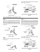
STEP 3
Threadone end of 1/4 in. X3in. brass nipple into
bottom of pressure switch. Thread other end into left
1/4 in. hole of tank cross. Thread pressure gauge into
right 1/4 in. hole of tank cross. Cut and cement as many
sections and couplings of PVC pipe needed to connect
the 1 in. male PVC adapter to pump discharge.
PRESSURE
SWITCH
PRESSURE
GUAGE
1/4 in. X 3 in.
NIPPLE
Figure 3: Step 3
The complete installation should look like the drawing
shown below. See Figure 4.
PRESSURE
GAUGE
PRESSURE
SWITCH
OPTIONAL
GATE VALVE
TO
WELL
MALE PVC
ADAPTER
PRESSURE
RELIEF VALVE/
BOILER DRAIN/
STREET TEE
1/4 in. PLUG
TO
SYSTEM
VALVE
BASE MOUNTED JET PUMP WITH VERTICAL TANK
Figure 4