
Operating Guide


5
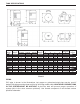
TANK SPECIFICATIONS
Tank
Model
Capacity in
Gallons
Drawdown in Gallons
Prechg.
Pressure
Dimensions in Inches
Discharge
Connection
Weight
In
Pounds
A
BC D E
LPT2
2 0.7 0.6 —
25 PSI
10-3/16 —
8-1/4
—
3/4 in. NPTM
5.0
LPT5
5 1.6 1.4 —
25 PSI
14-3/4 — 11 —
3/4 in. NPTM
9.0
LPT7
7 2.5 2.1 —
25 PSI
21-1/16
—11 —
3/4 in. NPTM
14.0
LPT14 14 5.2 4.3 3.7
25 PSI
24-3/4
2-1/4
15-3/8
—
1 in. NPTF
25.5
LPT20 20 7.4 6.2 5.4
25 PSI
32-3/4 2-1/4
15-3/8
—
1 in. NPTF
30.0
LPT36 36
13.3
11.1
9.7
25 PSI
32-3/8 2-1/4
20 —
1 in. NPTF
45.0
LPT52 52
19.2
16.1
14
25 PSI
38-5/8 2-1/4
23-3/8
—
1-1/4 in. NPTF
77.0
LPT86 86
31.8
26.7
23.2
25 PSI
58-3/4 2-1/4
23-3/8
—
1-1/4 in. NPTF
105.0
LPT119 119 44 37 32
25 PSI
61-1/4
2-1/2
26 —
1-1/4 in. NPTF
165.0
LPT7H
7 2.5 2.1 —
25 PSI
12-7/8
21-1/8
11
12-1/2
3/4 in. NPTM
16.0
LPT20H
20 7.4 6.2 5.4
25 PSI
17-3/8
27-1/8
15-3/8
12-1/2
1 in. NPTM
30.0
LMT20
20 7.4 6.2 5.4
25 PSI
32-3/4 2-1/4
15-3/8
—
1 in. NPTF
33.0
LMT36
36
13.3
11.1
9.7
25 PSI
32-3/8 2-1/4
20 —
1 in. NPTF
47.5
LMT52
52
19.2
16.1
14
25 PSI
38-5/8 2-1/4
23-3/8
—
1-1/4 in. NPTF
79.5
LMT86
86
31.8
26.7
23.2
25 PSI
58-3/4 2-1/4
23-3/8
—
1-1/4 in. NPTF
108.0
LMT20H
20 7.4 6.2 5.4
25 PSI
17-1/2 31-3/8 15-3/8
12-1/2
1 in. NPTM
33.5
Chart 1
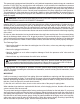
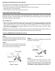
PIPING
desired. All piping must be clean and free of all foreign matter. ALL JOINTS AND CONNECTIONS
IN THE SYSTEM MUST BE AIRTIGHT. A pin-hole leak will prevent proper operation of
system (this is the most common problem). Use thread compound on all threads unless
specified otherwise.