ITEM # 0160655, 0160657, 0160669, 0160670, 0191809, 0160666, 0160668, 0191753, 0160677, 0191761, 0191762, 0160654, 0160659 PRE-PRESSURIZED DIAPHRAGM TANK MODEL # LPT14, LPT20, LPT36, LPT52, LPT86, LPT119, LMT20, LMT36, LMT52, LMT86, LPT2, LPT5, LPT7, LPT7H, LPT20H & LMT20H Français p. 13 Español p. 25 Questions, problems, missing parts? Before returning to your retailer, call our Technical Assistance Team at 1-800-549-6233, 7:00 a.m.-7:00 p.m., CST, Monday-Friday.
SAFE INSTALLATION USE AND SERVICE Your safety and the safety of others is extremely important in the installation, use and servicing of this water tank. Many safety-related messages and instructions have been provided in this manual and on your own water tank to warn you and others of a potential injury hazard. Read and obey all safety messages and instructions throughout this manual.
TABLE OF CONTENTS SAFE INSTALLATION USE AND SERVICE ................................................................................... 2 TABLE OF CONTENTS .................................................................................................................. 3 IMPORTANT INSTRUCTIONS BEFORE INSTALLATION ......................................................... 3, 4 FEATURES AND OPERATING CYCLES .......................................................................................
This pump tank is designed and intended for cold (ambient temperature) water storage at a maximum pressure of 100 PSIG, any use other than with cold water, or at a sustained or instantaneous pressure + !"" $%; <=$> ? > the system. The relief valve must be selected to pass the full capacity of the pump when the pressure in this tank is 100 PSIG or more. Consult pump manufacturer for pump capacity at relief pressure.
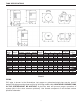
TANK SPECIFICATIONS Tank Model Capacity in Gallons LPT2 LPT5 LPT7 LPT14 LPT20 LPT36 LPT52 LPT86 LPT119 LPT7H LPT20H LMT20 LMT36 LMT52 LMT86 LMT20H 2 5 7 14 20 36 52 86 119 7 20 20 36 52 86 20 Drawdown in Gallons !" #$% 0.7 1.6 2.5 5.2 7.4 13.3 19.2 31.8 44 2.5 7.4 7.4 13.3 19.2 31.8 7.4 & ! #$% 0.6 1.4 2.1 4.3 6.2 11.1 16.1 26.7 37 2.1 6.2 6.2 11.1 16.1 26.7 6.2 " !' #$% — — — 3.7 5.4 9.7 14 23.2 32 — 5.4 5.4 9.7 14 23.2 5.4 Prechg.
DRAINING FOR SERVICING OR FOR WINTER The system should be drained before it is disconnected for servicing, or if it is inoperative for an extended Q Z _ ` @ _ q DIAPHRAGM TANK INSTALLATION Diaphragm tanks are recommended for clear water applications.
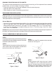
The complete installation should look like the drawing shown below. See Figure 4. PRESSURE RELIEF VALVE *0 67%5(9 DRAIN SUBMERSIBLE PUMP WITH VERTICAL TANK ) &+ $ " ) " TYPICAL JET PUMP INSTALLATION STEP 1 Z !" ~ ! Z tank cross into nipple so that the two 1/4 in. holes in tank cross face upward. Thread street tee into front of tank cross. Thread pressure relief valve into top of street tee and thread 3/4 in. boiler drain into front of street tee.
JET PUMP MOUNTED ON HORIZONTAL TANK GATE VALVE PRESSURE SWITCH JET PUMP WITH IN-LINE TANK TO SYSTEM JET PUMP MOUNTED ON VERTICAL TANK TO SYSTEM RELIEF VALVE PRESSURE SWITCH TO WELL PRESSURE SWITCH UNION [ 9(\;%9(<] CHECK VALVE RTA ADAPTER SUCTION PIPE DRAIN DRAIN NOTE: NO PRESSURE RELIEF VALVE SHOWN ON JET PUMP WITH IN-LINE DRAWING AND JET PUMP MOUNTED ON VERTICAL TANK DRAWING. to the right. Consult your local pump professional for your particular installation.
NOTES 9
NOTES 10
NOTES 11
WARRANTY !_(49 5%2% (< `4994= _ 7= 5# { 52 #;2# 4=|$ {Z ^ @| { | @ $ @ Q + % case of a defect, malfunction or failure to conform to this warranty, the Company will repair or replace this tank. No labor, installation or freight (if any) charges are included in this warranty. You must pay these costs.
ARTICLES # 0160655, 0160657, 0160669, 0160670, 0191809, 0160666, 0160668, 0191753, 0160677, 0191761, 0191762, 0160654, 0160659 RÉSERVOIR POUR POMPE MODÈLES # LPT14, LPT20, LPT36, LPT52, LPT86, LPT119, LMT20, LMT36, LMT52, LMT86, LPT2, LPT5, LPT7, LPT7H, LPT20H et LMT20H } 4=$% =$){ '* & Des questions, des problèmes, des pièces manquantes? Avant de retourner le produit Q ! "" X'qqQ 7 h et 19 h (HNC), du lundi au vendredi.
INSTALLATION, UTILISATION ET ENTRETIEN SÉCURITAIRE { < { { qui se trouvent dans ce guide.
TABLE DES MATIÈRES INSTALLATION, UTILISATION ET ENTRETIEN SÉCURITAIRES...................................................... 14 TABLE DES MATIÈRES ...................................................................................................................... 15 DIRECTIVES IMPORTANTES À LIRE AVANT DE COMMENCER L’INSTALLATION .................. 15, 16 CARACTÉRISTIQUES ET CYCLES DE FONCTIONNEMENT .......................................................... 16 CARACTÉRISTIQUES DU RÉSERVOIR ................
Ce réservoir est conçu pour recevoir de l’eau froide (température ambiante) à une pression maximale de 100 lb/po2 Z Q Q @ 100 lb/po2Q >$ $^<%Z>%? % !"" ^
CARACTÉRISTIQUES DU RÉSERVOIR Modèle de < litres LPT2 LPT5 LPT7 LPT14 LPT20 LPT36 LPT52 LPT86 LPT119 LPT7H LPT20H LMT20 LMT36 LMT52 LMT86 LMT20H 7,57 18,93 26,50 53 75,71 136,27 196,84 325,55 450,46 26,50 75,71 75,71 136,27 196,84 325,55 75,71 < " 0 0,7 1,6 2,5 5,2 7,4 13,3 19,2 31,8 44 2,5 7,4 7,4 13,3 19,2 31,8 7,4 & b/po " ' lb/po 0,6 – 1,4 – 2,1 – 4,3 3,7 6,2 5,4 11,1 9,7 16,1 14 26,7 23,2 37 32 2,1 – 6,2 5,4 6,2 5,4 11,1 9,7 16,1 14 2
%<4=X( #7;9 5(= 9( %(= 7; (= #9%$%7= <( 5~%(9 @ Q ` Q @ + [ "Q! {q | INSTALLATION DU RÉSERVOIR À MEMBRANE
ci-dessous : Voir la figure 4.
POMPE À JET INSTALLÉE SUR UN RÉSERVOIR HORIZONTAL ROBINETVANNE PRESSOSTAT VERS LE SYSTÈME POMPE À JET INSTALLÉE SUR UN RÉSERVOIR VERTICAL POMPE À JET AVEC RÉSERVOIR EN LIGNE SOUPAPE DE DÉCHARGE RACCORD [ 9(\;%$] VERS LE SYSTÈME PRESSOSTAT VERS LE PUITS CLAPET DE NON-RETOUR ADAPTATEUR RTA TUYAU <4$#%94 %7= PRESSOSTAT DRAIN DRAIN REMARQUE : IL N’Y A PAS DE SOUPAPE DE DÉCHARGE ILLUSTRÉE SUR LA POMPE À JET INSTALLÉE SUR LE RÉSERVOIR EN LIGNE NI SUR LA POMPE À JET INSTALLÉE SUR LE RÉSERVOIR VER
REMARQUES 21
REMARQUES 22
REMARQUES 23
GARANTIE X494= %( 5%2% ( <( 4=$ $;9 5($ 9$(97%9$ #7;9 #72#($ <( 27<5($ 5# ( 52 ( ? | { | Q Q + $ Q Q ?
ITEM # 0160655, 0160657, 0160669, 0160670, 0191809, 0160666, 0160668, 0191753, 0160677, 0191761, 0191762, 0160654, 0160659 TANQUE PARA BOMBAS MODELO # LPT14, LPT20, LPT36, LPT52, LPT86, LPT119, LMT20, LMT36, LMT52, LMT86, LPT2, LPT5, LPT7, LPT7H, LPT20H y LMT20H } =$)04=$% '*!X & ¿Preguntas, problemas, piezas faltantes? Antes de volver a la tienda, llame a nuestro ! "" X'qqQ Q estándar, de lunes a viernes.
INSTALACIÓN, USO Y REPARACIONES SEGUROS Su seguridad y la seguridad de otros son extremadamente importantes al instalar, usar y realizar el mantenimiento de este tanque de agua. En este manual y en su propio tanque de agua se han proporcionado muchos mensajes e instrucciones realacionadas con la seguridad para advertirle y advertir a otros de los peligros de posibles lesiones. Lea y cumpla con todos los mensajes e instrucciones de seguridad en este manual.
ÍNDICE INSTALACIÓN, USO Y MANTENIMIENTO SEGUROS ............................................................... 26 ÍNDICE .......................................................................................................................................... 27 INSTRUCCIONES IMPORTANTES ANTES DE LA INSTALACIÓN ....................................... 27, 28 CARACTERÍSTICAS Y CICLOS OPERATIVOS........................................................................... 28 ESPECIFICACIONES DEL TANQUE ...
? ¤ £ { | ¡+ !"" $%;Q ¡ !"" $%; es INSEGURA. Se debe incorporar en el sistema una válvula de seguridad del tamaño adecuado. La válvula sea de 100 PSIG o más.
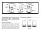
ESPECIFICACIONES DEL TANQUE 7,4 PULG. 9,3 PULG.
DRENAJE POR REPARACIONES O POR EL INVIERNO ? Q ¡ prolongado o si corre el riesgo de congelarse.
La instalación completa debe verse como el siguiente dibujo. Consulte la figura 4.
BOMBA DE CHORRO MONTADA SOBRE TANQUE HORIZONTAL GATE DESCARGA Interruptor de presión BOMBA DE CHORRO CON TANQUE EN LÍNEA AL SISTEMA Válvula de descarga BOMBA DE CHORRO MONTADA SOBRE TANQUE VERTICAL AL SISTEMA Interruptor de presión AL POZO UNIÓN [$( 9(\;%(9(= ] Válvula de control RTA ADAPTADOR Interruptor de presión TUBO DE SUCCIÓN DESAGÜE DESAGÜE NOTA: NO SE MUESTRA NINGUNA VÁLVULA DE DESCARGA DE PRESIÓN EN EL DIBUJO DE LA BOMBA DE CHORRO CON EL TANQUE EN LÍNEA Y EL DIBUJO DE LA BOMBA DE CHORR
NOTAS 33
NOTAS 34
NOTAS 35
GARANTÍA GARANTÍA LIMITADA DE CINCO AÑOS PARA LOS TANQUES DE BOMBA LPT Y LMT { ^ ¤£ | ¡ { | ¤ Q Q @ ? Q £ Q ^ ¤£ ¡ ¡ ? £ @ envío (de haber).