
Use and Care Guide


4
Lowes.com
PLANNING INSTALLATION
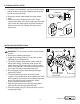
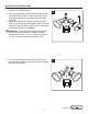
2. For under-eave installation, the sensor head must be
rotated as shown for proper operation and to avoid
the risk of electrical shock.
a. Swing the sensor head toward the clamp screw
joint.
b. Rotate the sensor head clockwise 180° so the
controls face down. If the sensor pops out of the ball
joint, loosen the clamp screw and push the sensor
back into the ball joint. Tighten the clamp screw
when done.
Controls
Clamp
Screw
Controls
Controls
2
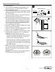
INSTALLATION INSTRUCTIONS
1. Mount the Light Control:
WARNING: Turn the power off at the circuit breaker
or fuse.
a.
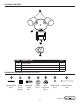
b. Install the mounting strap (CC) using two screws
c. The plastic hanger (GG) can be used to hold the
plastic hanger (GG) through the hole in the center
of the cover plate (B). The small end then goes into
one of the slots on the mounting strap (CC).
d. Route the light control’s wires through the large
gasket (DD) holes.
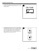
e.
together. Connect the black wires together, the white
wires together, and connect the junction box ground
Secure with wire connectors (EE).
f. Align the light control cover plate (B) and gasket
(DD). Secure with the mounting bolt (AA).
g.
mounting bolt (AA).
1
CC
White to white
EE
Junction box ground
wire to green ground
screw on fixture.
Black to black
AA
DD
B
BB
FRONT
FF