ITEM #1143421 TILT TV WALL MOUNT MODEL #UT175TP Español p. 15 ATTACH YOUR RECEIPT HERE Serial Number Purchase Date Questions, problems, missing parts? Before returning to your retailer, call our customer service department at 1-866-994-4148, 8 a.m. - 8 p.m., EST, Monday - Sunday.
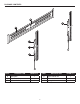
PACKAGE CONTENTS B D A C E F PART DESCRIPTION A Wall plate B Bubble level C Left vertical rail QUANTITY 1 1 1 PART DESCRIPTION D Right vertical rail E Tilt lever F Spring lock 2 QUANTITY 1 2 2
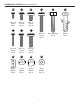
HARDWARE CONTENTS (shown actual size) AA CC DD M4 x 12 Screw Qty. 4 M6 x 15 Screw Qty. 4 M8 x 15 Screw Qty. 4 EE GG HH FF II JJ M8 x 50 Screw Qty. 4 8 mm Lag bolt Qty. 4 Anchor Qty. 4 M4 x 30 Screw Qty. 4 M6 x 30 Screw Qty. 4 M8 x 30 Screw Qty. 4 KK LL MM NN Square washer Qty. 4 5 mm Spacer Qty. 4 10 mm Spacer Qty. 4 Steel washer Qty.
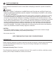
SAFETY INFORMATION Please read and understand this entire manual before attempting to assemble, operate or install the product. WARNING • FAILURE TO READ, THOROUGHLY UNDERSTAND, AND FOLLOW ALL INSTRUCTIONS CAN RESULT IN SERIOUS PERSONAL INJURY, DAMAGE TO PERSONAL PROPERTY, OR VOIDING OF FACTORY WARRANTY. • Do not attempt to install or assemble this product if the product or hardware is damaged or missing.
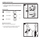
M8 x 15 Screw KK Square washer FF MM AA DD II CCNN 5 M6 x 30 Screw Qty. 4 LL KK x4 M4 x 30 Screw Qty. 4 EE HH x4 GG EE x4 M8 x 50 Screw Qty. 4 x4 GG GG 1 Tip: 5 mm spacers (LL) and/or 10 mm spacers (MM) can also be used to provide clearance for cables and connectors. 2 NNKK MM LL x 30 M6 x 30M4 x 30 M4M8 x 30 M8 x 30 M6 x 30 Screw Screw ScrewScrewScrew Screw Qty. Qty. 4 4 Qty. 4 Qty. 4Qty. 4Qty. 4 * M8 x 30 Screw Qty. 4 NN MM II FF NN M8 xb Anchor 8 mm Lag Qty. 4Qty.Scre 4 Qty.
M8 x 50 8 mm Lag bolt Anchor Screw Qty. 4Qty. 4Qty. 4 EE M4 x 30 Screw GG M6 x 30 Screw HH M8 x 30 Screw FF M8 x 50 Screw KK Square washer LL 5 mm Spacer MM 10 mm Spacer KKMM LL NN KK MM LL NN MM M8 x 50NN Screw Qty. 4 x4 x4 6 LL x4 KK MM x4 NN 10 mm Square Spacer washer Qty. Qty. 4 4 5 mmSteel Square10 mm5 mm washer Spacer washerSpacer Spacer Qty. 12 Qty. 4 Qty. 4 Qty. 4Qty. 4 ** 5 mm Spacer Qty. 4 x4 NN MM 1 Steel 10 mm washer Spacer Qty. Qty. 12 4 KK Steel washer Qty.
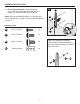
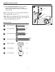
5 mm Spacer Qty. 4 Wood Stud Installation Note: For concrete, proceed to step 7. Square washer Qty. 4 3. U se a stud finder (not included) to locate wood studs. Mark the edge and center locations. Square 10 mm washer Spacer Qty. 4 Qty. 4 KKMM x4 5 mm 10 mm Steel Square Spacer Spacer washerwasher Qty. 4 Qty. 4 Qty. 12 Qty. 4 LL NN 10 mm Spacer KK MM NN MM M8 x 30 Screw Qty. 4 Steel washer Qty. 12 NN M8 x 50 Anchor 8 mm Lag bolt Screw Qty. 4Qty. 4 Qty. 4 2.
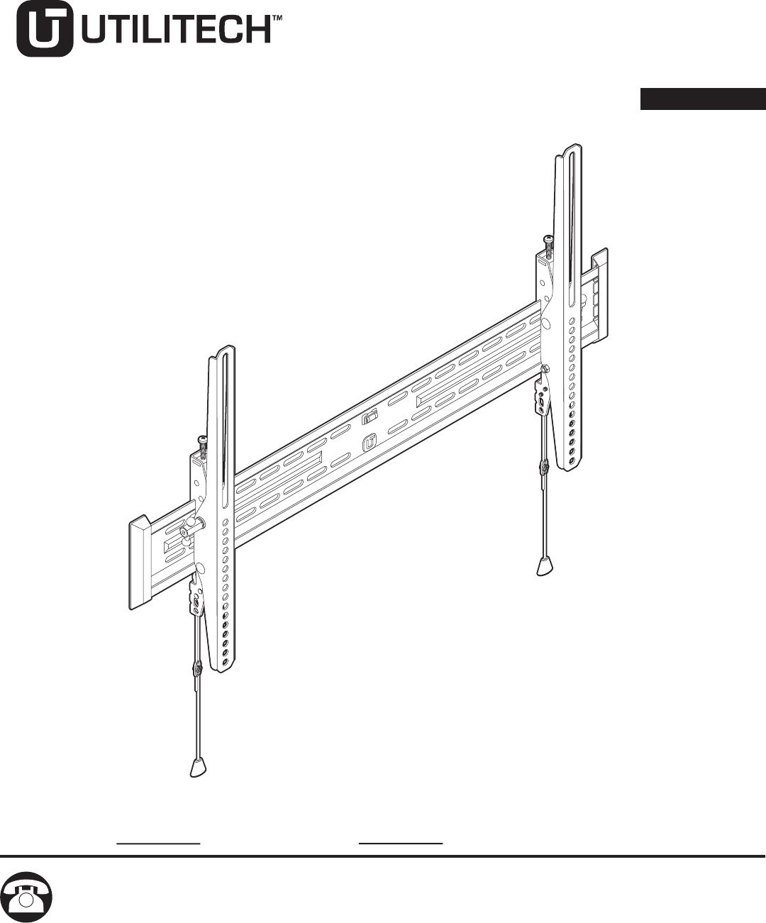
ASSEMBLY INSTRUCTIONS 4 4. U se wall plate (A) to mark four mounting hole locations. Note: Use bubble level (B) to level wall plate (A). A B 5 Anchor Qty. 4 Anchor Qty. 4 5. Drill four 7/32 in. pilot holes 2-1/3 in. (60 mm) deep at the marked locations for the mounting holes. A 1 NN H 8 Steel washer Qty. 12 NN 2 m cer .4 MM 15 ew .4 M8 x 30 Screw Qty. 4 II x4 NN Steel washer M II x4 FF NN 8 mm Lag bolt D M8 x 50 Screw Qty.
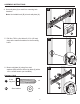
ASSEMBLY INSTRUCTIONS 7 Concrete Installation 7. Use wall plate (A) to mark four mounting hole locations. Note: Use bubble level (B) to level wall plate (A). A B 8. Drill four 3/8 in. pilot holes 2-3/4 in. (70 mm) deep at the marked locations for the mounting holes. 8 9. I nsert anchors (JJ) into holes. Tap with hammer (not included) if necessary. 9 1 JJ Anchor x4 1 8 mm Lag bolt Qty. 4 2 JJ r 9 0 II JJ Anchor Qty.
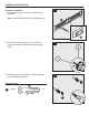
12. Pull spring locks (F) down and push bottom of panel toward wall. Release spring locks (F) when panel is secure. F 1 10 M8 x 30 Screw Qty. 4 MM x4 11 5 mm Spacer Qty. 4 LL x4 Steel washer Qty. 12 II D C 12 2 F 10 mm Spacer Qty. 4 NN 10 mm M8 x 50Steel 8 mm Lag bolt Spacer Screw washer Qty. 4 Qty. 4 Qty. 4Qty. 12 A Square washer Qty. 4 KK 5 mm Spacer Qty. 4 HH NN Hardware Used M6 x 30 Screw Qty. 4 Square washer Qty. 4 GG MM Final Installation 11.
ASSEMBLY INSTRUCTIONS 13 3 2 13. To adjust tilt, loosen both tilt levers (E) and move panel to desired position. Tighten both tilt levers (E) to hold desired tilt. -3°–12° 2 Note: For clarity, illustration is shown with panel removed. or E 3 5 mm or 1 3 1/2 in. Additional Security (Optional) 14. Secure panel with 7 mm pad lock (not included) for theft security.
ASSEMBLY INSTRUCTIONS Leveling 1. Adjust the screws on the vertical rails to level the flat panel. 1 Strap Features 1. Squeeze and hold control to change cord length. 1 Note: The pendant can be attached to either the wall plate or the vertical rails with magnet.
WARRANTY This product is covered against defects in materials and workmanship for 5 years. The manufacturer will repair or replace the defective component or product, at its sole discretion. Failure to follow product care instructions from the manufacturer will void the warranty. To obtain warranty service, contact customer service at 1-866-994-4148. You must supply a copy of your original receipt. If your product must be shipped for inspection, you will be responsible for the shipping charges.
Printed in China 14
ARTÍCULO #1143421 CON INCLINACIÓN SISTEMA PARA MONTAJE DE TV EN LA PARED MODELO #UT175TP ADJUNTE SU RECIBO AQUÍ Número de serie Fecha de compra ¿Preguntas, problemas, piezas faltantes? Antes de volver a la tienda, llame a nuestro Departamento de Servicio al Cliente al 1-866-994-4148, del lunes a domingo de 8 a.m. a 8 p.m., hora estándar del este.
CONTENIDO DEL PAQUETE B D A C E F PIEZA DESCRIPCIÓN A Placa para pared B Nivel de burbuja C Riel vertical izquierdo CANTIDAD 1 1 1 PIEZA DESCRIPCIÓN D Riel vertical derecho E Palanca inclinable F Resorte de bloqueo 16 CANTIDAD 1 2 2
ADITAMENTOS (se muestran en tamaño real) AA CC DD Tornillo M4 x 12 Cant. 4 Tornillo M6 x 15 Cant. 4 Tornillo M8 x 15 Cant. 4 EE GG HH Tornillo M4 x 30 Cant. 4 KK Tornillo M6 x 30 Cant. 4 LL FF II JJ Tornillo M8 x 50 Cant. 4 Tirafondo de 8 mm Cant. 4 Ancla de expansión Cant. 4 Tornillo M8 x 30 Cant. 4 MM Arandela Espaciador Espaciador cuadrada de 5 mm de 10 mm Cant. 4 Cant. 4 Cant. 4 NN Arandela de acero Cant.
INFORMACIÓN DE SEGURIDAD Lea y comprenda completamente este manual antes de intentar ensamblar, usar o instalar el producto. ADVERTENCIA • ASEGÚRESE DE LEER, COMPRENDER Y SEGUIR LAS INSTRUCCIONES ADECUADAMENTE; DE LO CONTRARIO, PUEDEN OCASIONARSE LESIONES PERSONALES GRAVES, DAÑOS A LA PROPIEDAD O ANULACIÓN DE LA GARANTÍA DE FÁBRICA. • No intente instalar o ensamblar el producto si faltan algunas piezas o los aditamentos están dañados.
Tornillo M8 x 50 Cant. 4 EE GG LL NN KK MM LL Tornillo Tornillo Tornillo Tornillo Tornillo Tornillo M8x x3030 M6 x 30M4 x 30M8 xM6 M4 30x 30 Cant.4 4 Cant. 4 Cant. 4 Cant. Cant. 4 4 Cant. Sugerencia: se pueden utilizar también espaciadores de 5 mm (LL) y de 10 mm (MM) para que haya separación entre cables y conectores. MM KK HH Tornillo M8 x 15 Cant. 4 DD JJ II FF An ex C NN MM Tornillo M8 x 30 Cant. 4 NN Tirafondo de 8Tornillo mm Ancla de Tornillo Tirafondo de 8 m M8 x 50 M8 Cant.
LL KK AADD CC FF AA EE Tornillo M4 x 30 GG Tornillo M6 x 30 HH Tornillo M8 x 30 FF Tornillo M8 x 50 KK Arandela cuadrada LL Espaciador de 5 mm MM Espaciador de 10 mm LL NN KK MM LL NN MM x4 x4 x4 x4 20 MM Arandela Espaciador Espaciador LL x4 ** KK x4 HH NN MM Tornillo M8 x 30 Cant.
Instalación en vigas de madera Nota: para paredes de concreto, continúe con el paso 7. KK MM LL NN LL Espaciador de 5 mm MM Espaciador de 10 mm MM KK LL Tornillo Tornillo Tornillo M8 x 30 M6 x 30 M4 x 30 Cant. Cant. 4 4 Cant. 4 NN MM Tornillo M8 x 30 Cant. 4 2. S i los tornillos son demasiado largos, podrían ser necesarios más espaciadores de 5 mm (LL), espaciadores de 10 mm (MM) y arandelas de acero (NN).
INSTRUCCIONES DE ENSAMBLAJE 4. Utilice una placa para pared (A) para marcar las ubicaciones de los cuatro orificios de montaje. 4 Nota: utilice un nivel de burbuja (B) para nivelar la placa para pared (A). A B 5 Ancla de expansión Cant. 4 5. T aladre cuatro orificios guía de 7/32 pulg. con 2-1/3 pulg. (60 mm) de profundidad en las ubicaciones marcadas para los orificios de montaje. Aditamentos utilizados 6 A 1 NN x4 II 2 Arandela de acero Cant.
INSTRUCCIONES DE ENSAMBLAJE Instalación en pared de concreto 7. Utilice una placa para pared (A) para marcar las ubicaciones de los cuatro orificios de montaje. 7 Nota: utilice un nivel de burbuja (B) para nivelar la placa para pared (A). A B 8. T aladre cuatro orificios guía de 3/8 pulg. con 2-3/4 pulg. (70 mm) de profundidad en las ubicaciones marcadas para las orificios de montaje. 8 9. I nserte las anclas de expansión (JJ) en los orificios.
Instalación final 11. Cuelgue el riel vertical derecho (C) y el izquierdo (D) en la placa para pared (A). HH GG EE NN Tirafondo de 8 mm II Aditamentos utilizados x4 x4 12. Jale los resortes de bloqueo (F) hacia abajo y presione la parte inferior del panel contra la pared. Una vez asegurado el panel, libere los resortes de bloqueo (F). 24 F 1 LL MM Tornillo M8 x 30 Cant. 4 11 Arandela de acero Cant. 12 NN A II C A 12 2 F Arandela Espaciador Espaciador cuadrada de 5 mm de 10 mm Cant.
INSTRUCCIONES DE ENSAMBLAJE -3°–12° Nota: para obtener una explicación más clara, vea la ilustración del panel retirado. 3 2 13 13. Para ajustar la inclinación, afloje las palancas de inclinación (E) y mueva el panel a la posición deseada. Apriete las palancas de inclinación (E) para mantener la inclinación deseada. 2 o E 3 5 mm o 1 3 1/2 pulg. 14 Seguridad adicional (opcional) 14. Asegure el panel con candados de 7 mm (no se incluyen) para evitar robos.
INSTRUCCIONES DE ENSAMBLAJE Nivelación 1. Ajuste los tornillos en los rieles verticales para nivelar el panel plano. 1 Características de la correa 1. Apriete y mantenga presionado el control para cambiar el largo delcordón. 1 Nota: la lámpara colgante puede conectarse a la placa de pared en los rieles verticales con el imán.
GARANTÍA Este producto tiene garantía contra defectos en los materiales y mano de obra por 5 años. El fabricante reparará o reemplazará el componente o producto defectuoso según su criterio. El incumplimiento de las instrucciones del fabricante acerca del cuidado del producto anulará la garantía. Para obtener el servicio de garantía, llame al Departamento de Servicio al Cliente al 1-866-994-4148. Deberá proporcionar una copia del recibo original.
Impreso en China 28