
Installation Guide

8
ASSEMBLY INSTRUCTIONS
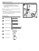
1
2
6
A
II
NN
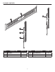
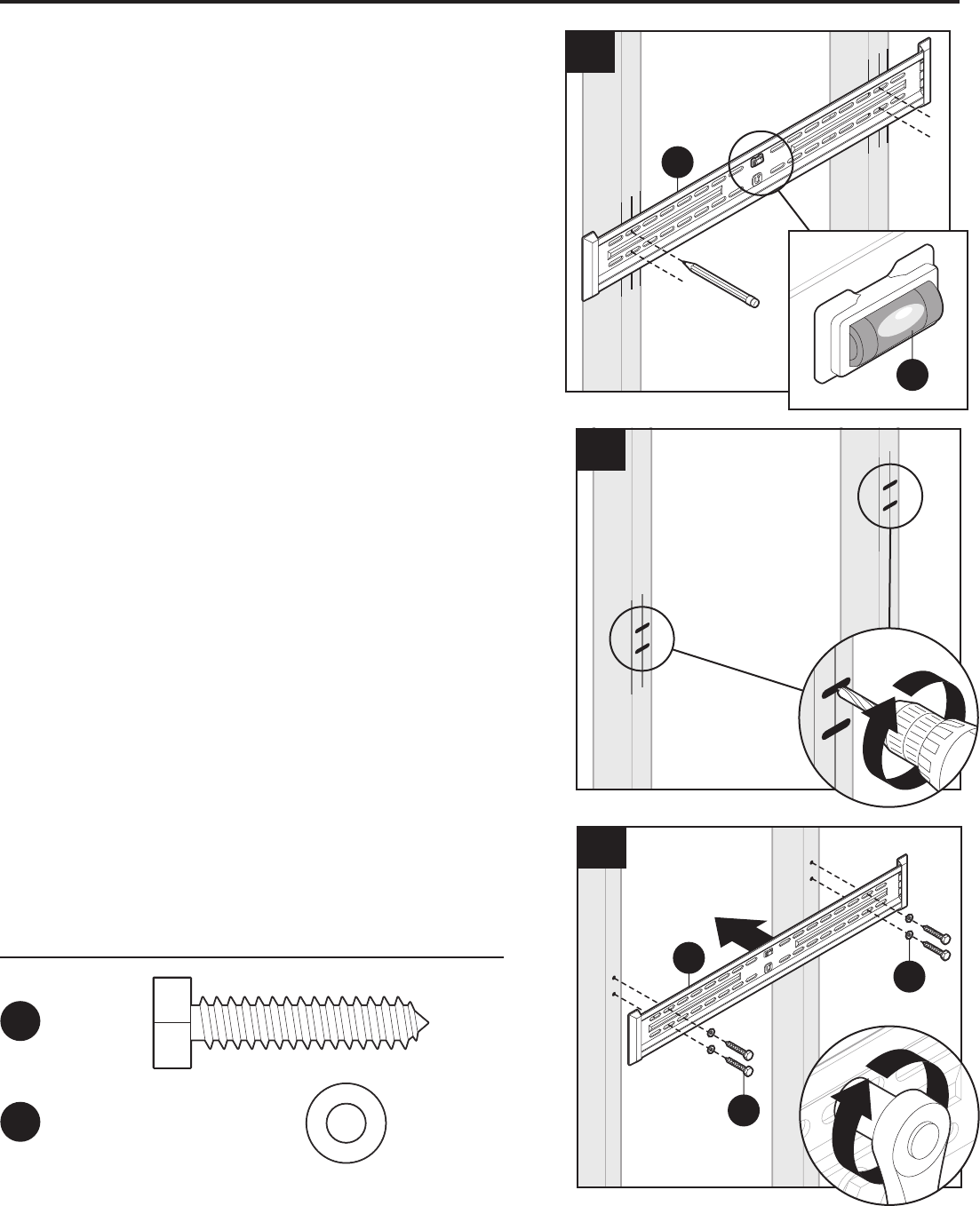
6. Mount wall plate (A) using four steel
washers (NN) and four 8 mm lag bolts (II) with a
1/2 in. socket wrench (not included).
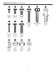
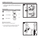
Hardware Used
II
x 4
8 mm
Lag bolt
M4 x 12
Screw
Qty. 4
AA
M6 x 15
Screw
Qty. 4
CC
M8 x 15
Screw
Qty. 4
8 mm Lag bolt
Qty. 4
Anchor
Qty. 4
DD FF
M4 x 30
Screw
Qty. 4
EE
M6 x 30
Screw
Qty. 4
GG
M8 x 30
Screw
Qty. 4
HH
M8 x 50
Screw
Qty. 4
Square
washer
Qty. 4
KK
5 mm
Spacer
Qty. 4
LL
10 mm
Spacer
Qty. 4
MM
Steel
washer
Qty. 12
NN
II
JJ
NN
x 4
Steel washer
M4 x 12
Screw
Qty. 4
AA
M6 x 15
Screw
Qty. 4
CC
M8 x 15
Screw
Qty. 4
8 mm Lag bolt
Qty. 4
Anchor
Qty. 4
DD FF
M4 x 30
Screw
Qty. 4
EE
M6 x 30
Screw
Qty. 4
GG
M8 x 30
Screw
Qty. 4
HH
M8 x 50
Screw
Qty. 4
Square
washer
Qty. 4
KK
5 mm
Spacer
Qty. 4
LL
10 mm
Spacer
Qty. 4
MM
Steel
washer
Qty. 12
NN
II
JJ
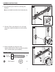
4
A
B
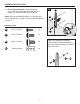
4. Use wall plate (A) to mark four mounting hole
locations.
Note: Use bubble level (B) to level wall plate (A).
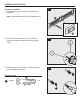
5
5. Drill four 7/32 in. pilot holes 2-1/3 in. (60 mm)
deep at the marked locations for the mounting
holes.