Tools Needed: (A) 1 long “L” shaped tube (B) 1 short “L” shaped tube (D) 1 long straight tube (C) 1 “U” shaped tube (E) 1 short tube with hole (G) 2 flared tubes (F) 2 long tubes with tapered ends Thank you for purchasing Utopia Alley Products.Please contact us if you have difficulty with assembly or need replacement parts. Utopia Alley customer service is here to assist you. Email: CustomerService@utopiaalley.com Please attach your name and Order ID so that we can assist you better .
(I) 1 closed metal flange (H) 2 open metal flanges (K) 1 rubber pipe stabilizer (L) 2 metal inserts (J) 1 pipe bracket NOTE: For parts M & N, 1 in. and 7/8 in. refers to the diameter of the circular end that will fit inside tubes (D,G) (M) 2 1 in. nylon insert (O) 3 large screws (N) 1 7/8 in.
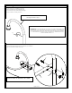
Mounting Instructions 1.Wrap rubber pipe stabilizer (K) around the showerhead pip approximately 80 in. from the floor (or at the desired height for your shower curtain),as shown. existing showerhead pipe K IMPORTANT: If your showerhead pipe comes out of the wall instead of up from the tub spout and handles (see photo on page 1), your installation will vary from these instructions.
3. Measure distance from long “L” shaped tube (A) to wall. A me as ure thi sd ista nc e 4.Subtract 1/8 in. from the measurement in step 3. Measuring from the flared-end of the tube, mark this measurement on flared tubes (G). Using a hacksaw, cut flared tubes (G) at the mark. NOTE: Before you cut, make sure you measured from the flared-end of the tube. discard this end cut here dis IMPORTANT: Be sure to subtract 1/8 in. to the measurement from step 3.
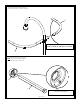
.Screw a large screw (O) into one of the metal inserts (L). NOTE: Be sure flares are pointing toward the head of the bolt. Continue to screw the large screw in until it begins to come out the other end of metal insert (L). Repeat using other metal insert (L) and another large screw (O). O L IMPORTANT: Be sure flares point toward the head of the screw.
.Holding large screw (O) and using a hammer, gently tap the head of the screw to drive metal insert (L) into a flared tube (G). IMPORTANT: Metal insert (L) must be inserted in the tube between 5/8 in. and 3/4 in. DO NOT INSERT THE METAL INSERT MORE THAN 3/4 in. NOTE: Use the screw to gauge that metal insert (L) is going into the tube straight. You can straighten the metal insert by gently straightening the screw. Repeat using other large screw (O), metal insert (L) and flared tube (G). G L O 7.
8. Insert the tapered end of short “L” shaped tube (B) into longer side (end with 4 holes) of long “L” shaped tube (A). B screw hole in bottom of tube A 9.Slide an open metal flange (H) onto each cut flared tube (G), as shown. NOTE: Back of open metal flange (H) faces the flared end of tube (G).
10.Insert a 1 in. nylon insert (M) into each cut flared tube (G). Fasten 2 cut flared tubes (G) to long “L” shaped tube (A), and short “L” shaped tube (B) using large screws (O). O M A B G G L NOTE: If nylon inserts (M) can’t be inserted inside of flared tubes (G), metal inserts (L) may need to be inserted a little farther into flared tubes (G). (See step 6.
11.Mark mounting points on wall through holes in metal flanges (I). NOTE: If a mounting screw (S) will be going directly into a stud, an anchor (T) should not be used. Use a 1/4 in. (6 mm) drill bit for drywall anchor installation. Use a 5/64 in. (2mm) drill bit for direct stud installation. If installing into a material other than drywall or into stud, consult a professional for proper installation.
12.Attach the assembly to the wall. NOTE: If you screw directly into studs, anchors (T) are not necessary. S H 13.Fasten 2 long tubes with tapered ends (F) to the assembly using small screws (Q). IMPORTANT: For the rest of the installation, do not let the assembly just hang from the wall. A second person should continue to support the assembly until it is fastened to the ceiling.
14. Attach U-shaped tube (C) to the assembly using small screws (Q). NOTE: Make sure all of the small screws are attached to the bottom of the tubes, so the shower curtain rings will be able to slide freely along the top. C Q 15. Keeping assembly level, measure from the top of assembly to ceiling.
16. Subtract 2 in. from the measurement from step 15. Measuring from the end of the tube with the factory metal insert, mark this measurement on long straight tube (D). Using a hacksaw, cut long straight tube (D) at the mark. cut here factory metal insert dis discard this end ta D nc em inu s2 IMPORTANT: Be sure to subtract 2 in. from the measurement from step 15. Before you cut, make sure you measured from the end of the tube with the factory metal insert. 17.
18. Slide the long straight tube (D) that you previously cut into short tube with hole (E), as shown. factory metal insert E D 19. Insert 7/8 in. nylon insert (N) into the end of long straight tube (D). Fasten long straight tube (D) to the assembly using a large screw (O).
20. Slide short tube with hole (E) and closed metal flange (I) up to the ceiling. Mark mounting points on ceiling through holes in metal flange (I). NOTE: If a mounting screw (S) will be going directly into wood, an anchor (T) should not be used. If an anchor (T) will be used, use a 1/4 in. (6mm) drill bit for drywall anchor installation. Use a 5/64 in.(2mm) drill bit for direct stud installation. If installing into a material other than drywall or into stud, consult a professional for proper installation.
22. NOTE: Make sure the rod assembly is level. Fasten the set screw (U) into the vertical support collar (R) and tighten the short tube with hole (E) to the long straight tube (D) together using allen wrench (H), as shown. R D U filWARNING Manufacturer and seller expressly disclaim any and all liability for personal injury, property damage or loss, whether direct, indirect, or incidental, resulting from the incorrect attachment, improper use, inadequate maintenance, or neglect of this product.