
User's Manual
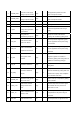
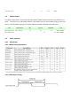
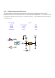

4 PHONE_PWR
3.8 volts +/-5% supply
voltage to phone module
High I
The application provides the main
power of the phone module
5 PHONE_PWR
3.8 volts +/-5% supply
voltage to phone module
High I
The application provides the main
power of the phone module
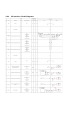
6 NC NA NA NA NA
7 GND Ground Low O System ground
8 V_REF
Reference Logic
Voltage level generated
by the Phone
High O
Provide the application with its logic
supply
9 RI
Ring Indicator
Generated by the phone
High O
The phone module indicates the
incoming call condition by pulling down
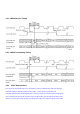
10 CAIT_RX
CAIT Receive Data
Input to the Phone
Low I
CAIT RX provides diagnostic signals
from the application to the phone using
AT commands
11 CAIT_TX
CAIT Transmit Data
Output from the Phone
NA O
CAIT TX provides diagnostic signals
from the application to the phone using
the monitor
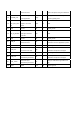
12 IG_IND
The Ignition status
indicator
High I
Ignition indicator provides the status of
the gnition. Ignition on condition is
indicated by pulling down and ignition off
condition is indicated by pulling up
13 HW_SD Hardware Shutdown High I
The phone module can be shut down by
pulling down
14 SD_REQ
Hardware Shutdown
request
High O
The phone module can request
hardwarw shutdown by pulling down and
it will be back to pull up after completion
of the hardware shut down
15 PHONE_WU
Reuest to wake_up the
phone from TCU
High I
Phone wake up is requested by pulling
down for 500ms
16 UART_DTR
UART Data terminal
ready to Phone from
TCU
High I
UART DTR provides the status signal
that indicates the TCU processor is
active when it is Low
17 UART_TX
UART Transimt from the
Phone to TCU
Low O
UART TX provides control signals from
the application to the phone using AT
commands
18 UART_RX UART Recevie to the Low I UART RX provides co signals from the