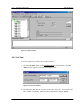
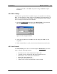
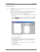
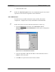
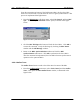
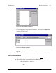
4-12 RPC/RP Configuration RPC/RP Manual Figure 4-13: RPC Window 4.2.1 Set Time To set the system time, follow the procedures below: 1. Click the Set Time option on the Configuration pull-down menu. The Set Time window appears, as shown in the figure below. Figure 4-14: Set Time Window 2. By default the RPC time is set to the current time of the PC. Set new date and time to RPC if necessary. Make necessary adjustment using the Arrow WLL-RPC/RP-IN/UM-1.
RPC/RP Manual RPC/RP Configuration 4-13 buttons in the fields. Click OK to accept the setting or Cancel to stop the transaction. 4.2.2 RPC Change Sometimes the operation data for an RPC may not be compatible to the hosting RPC. Use this function to make changes to the SDM (System Data Memory) so that it can accommodate the hosting RPC. Before making any change, the RPC device manager will disconnect from the RPC. 1. From the Configuration main menu, select RPC Change.
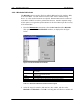
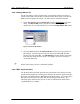
4-14 RPC/RP Configuration RPC/RP Manual 4.2.3.1 Blockade/Unblockade The Blockade option is used to block or unblock RP interface, E1 interface, RPs, or the entire RPC. Use this function to block traffic from a malfunctioning device. It is also used when units are replaced. Netman 2000 must be connected to the WLL/V5WLL in order to perform this function. Another important usage of this option is to regain the synchronization of the slave RPCs upon the recovery of the master RPC. 1.
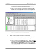
RPC/RP Manual RPC/RP Configuration 4-15 the units controlled by the RPC. No new calls will be accepted and all the calls in progress are allowed to complete and then dropped. 3. When the action is implemented, the system displays a message in the Self Message window, and the Status View window will also show the Blockade result, as illustrated in the figure below. Use the window to verify the result.
4-16 RPC/RP Configuration RPC/RP Manual 4.2.3.2 TimeSlot Layout F WARNING: Users are NOT recommended to make changes to the settings of the Time Slot. Use with caution! When connected to an RPC, use this function to reconfigure the RP control channel time slot. This function is used to complete the RP configuration and make it usable. This function applies to both RPCs and RPs. 1. Before configuring the time slot, use the Blockade function to block the target RPC or PC. 2.
RPC/RP Manual RPC/RP Configuration 4-17 7. Unblock the RPC or RP. F NOTE: The Time Slot Layout window is for configuration purpose only. Actual separation is done when the target RPC or RP is unblocked. 4.2.3.3 Maintenance Use this function to set RPC maintenance status, test RPs, and do other configuration. Eligible units are fully installed RPCs and installed RPs. F NOTE: General PSs can not use RP when maintenance is under way. 1.
4-18 RPC/RP Configuration RPC/RP Manual 4.2.3.4 Change Master RP For the operation in a group control mode, it sometimes becomes necessary to switch a master RP to a slave RP, because the master RP is faulty or because the NMS operation requires the switch. Use this feature to switch the function. 1. Select Unit Control, and then Master RP from the Maintenance pull-down menu. The Master RP window appears as shown in the figure below.
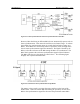
RPC/RP Manual RPC/RP Configuration 4-19 Figure 4-21: Clock Synchronization and Frame Synchronization in One RPC However, RPs that belong to different RPCs do not automatically operate with air frame synchronization. This causes the inefficienct air channel usage. To redress the problem, the synchronization group is created which includes as many as 8 RPCs. Those RPCs are connected by cables as open daisy chain, through which the air frame synchronization signal is transmitted.
4-20 RPC/RP Configuration RPC/RP Manual Upon the restoration and restart of the failed master RPC, the first slave RPC needs to be blocked and re-synchronized in order to regain synchronization. This process is implemented through Netman. 1. From the Maintenance pull-down menu, select Unit Control, and then RPC Sync. The RPC Synchronization window opens, as shown in the figure below. Figure 4-23: RPC Synchronization Window 2. Click the RPC blockage radio button to block the slave RPCs.
RPC/RP Manual RPC/RP Configuration 4-21 Figure 4-24: Select Online Trace Window 2. Click to highlight the target RP# and click OK. This opens the Online Trace window, as shown below. Figure 4-25: Online Trace Window 3. This window displays the relevant Time Slot status information about the target RP. 4.2.4 Function Status The Status option windows can be accessed through the Status pull-down menu.
4-22 RPC/RP Configuration RPC/RP Manual • • • RPs RP-I/F Board E1 Signal Node-I/F Board Air Channel TimeSlot Status Collect hourly traffic data for RPCs and RPs View configuration data for each RP control channel Verify configuration results 4.2.4.1 RPC Status 1. To view the status of the current RPC, click RPC from the Status option. Another way to open the RPC Status window is to click the RPC Status button. The RPC status is displayed on the Status View window, as shown in the figure below.
RPC/RP Manual RPC/RP Configuration Field Name ACT Program System SDM System Update Mode Mode Display Master Slave Sync. signal Trans. Sync. signal Stop Sync. between RPC Sync. Sync. between RPC Async. 4-23 Description The active SDM or PDM system for RPC running PDM system. There are two plane memory areas for the program data: N and E. Any one can be active or standby. SDM system. There are two plane memory areas for the operation data: N and E. Any one can be active or standby.
4-24 RPC/RP Configuration RPC/RP Manual Figure 4-27: RPs Operation Status View window Field Name Group Master RP# Inst. Power Trans. Layout Mainte Blockade Auto Maint Fault Warning RP Trans. Syn I/F Description The ID number of the group to which the RP belongs The sign * indicates the master RP. Radio port ID number Installation status. “Inst.” Indicates that the RP has been installed. The voltage of power. Usually it is 10mW. There are two power supply state: Pha.
RPC/RP Manual RPC/RP Configuration 4-25 time will be displayed in the box above the button, indicating the time when the data are updated. 3. With this window you can verify RP installation status, monitor alarms, power supply status, and transmission information, and identify areas of trouble. 4. If you want to view the status for an individual RP, you may access such a window by clicking the “+” sign to the left of RPs on the Unit View window. This displays all the RPs under the RPC.
4-26 RPC/RP Configuration RPC/RP Manual Figure 4-28: Status View window for One Individual RP WLL-RPC/RP-IN/UM-1.
RPC/RP Manual RPC/RP Configuration Field Name Node Address RP Number RPC Number RP Location RP Street Province/State RP Address (City) Zip/Postal Code Latitude (degree) Longitude (degree) RP information Master RP ID Power Type # of Antennas Survey ID Bureau ID Memo Mode Power Rating Fixture Type Serial Number RP Type Installed RP-RPC Line Information Impedance Box MDF In MDF Out Trunk RP Antenna Parameters Latitude Longitude Height RF Cable Length Elevation Azimuth Down Tilt Type Name Select Image Vie
4-28 RPC/RP Configuration RPC/RP Manual 5. The window in the above window may not display all the information in one screen. Use the horizontal and vertical scroll bars to see all the information. 4.2.4.3 RP-I/F Board Status With the RP-I/F Board Status View window you can view or verify such RP interface operational statuses as RP-IF#, installation, or warning. 1. To access the RP-I/F Status View window, click Status, then the Status option, and then the RP-I/F Board option.
RPC/RP Manual RPC/RP Configuration 4-29 4.2.4.4 E1 Signal Status Each RPC can have 4 E1 lines to communicate with the WLL/V5WLL. However, the D-channel can be established on only one E1 line. The E1 line on which the D-channel is established is named the master E1 and the other three E1 lines are named slave E1s. If the master E1 line is down, a slave E1 line will be promoted by the system to become the master E1. The D-channel can be established on this slave E1 line.
4-30 RPC/RP Configuration Field Name E1#1 E1#2 E1#3 E1#4 Layer 1 Layer 2 (SAPI=0) Layer 2 (SAPI=16) Layer 3 (SAPI=16) Master Slave Warning No warn RPC/RP Manual Definition Corresponding to E1-I/F#1, Bch#1 - 30 Corresponding to E1-I/F#2, Bch#31 - 60 Corresponding to E1-I/F#3, Bch#61 - 90 Corresponding to E1-I/F#4, Bch#91 - 120 Physical layer with SAPI=0,16 Data Link layer for call processing Data Link layer for HOST interface Network layer for HOST interface Master E1 on which D-channel is established.
RPC/RP Manual RPC/RP Configuration Field Name E1-IF# Inst Maint Fault Warn 4-31 Description E1 interface ID number Installation state configured by the system operation data. There are two states: Inst/Uninst. Blocked manually by HOST or RMT o indicates blockage. - indicates no blockage. Cut off from the operation system due to the unit trouble. o indicates the existence of error. - indicates no error exists. Warning status: o indicates the existence of warning - indicates no warning exists.
4-32 RPC/RP Configuration Field Name RP# T-ch# B-ch# Status(B-ch#) Status(T-ch#) RPC/RP Manual Definition RP ID number Traffic Channel ID number Bearer Channel ID number An o indicates the B channel enclosed in the parentheses is in use by the T channel number. In the example above, B channel 8 is in use by T channel 1. An o indicates the T channel enclosed in the parentheses is in use by the B channel number. In the example above, T channel 1 is in use by B channel 8.
RPC/RP Manual RPC/RP Configuration Field Name RP# Layout Multi-Frame Location Control Ch. Carrier Update 4-33 Description The ID number of the RP which transmits control channel LCCH Complete/Incomplete configuration. Complete: RP has found the control channel. Incomplete: RP has not been able to find the control channel (e.g. due to interference). Position to which the RP transmits control channel LCCH Channels over which the RP transmits control channel LCCH Retrieve the latest status information.
4-34 RPC/RP Configuration RPC/RP Manual Figure 4-34: Self Message Window This Self Message window displays only the event messages received from the RPCs that are connected to the host RT. In the above example the host RT has the IP address of 172.16.5 150. This RT controls 15 RPCs. The Self Message window is updated without the need for special operation action. 4.2.6 Reset RPC When a system component experiences trouble and the problem cannot be solved, it may be necessary to reset that component.
RPC/RP Manual RPC/RP Configuration 4-35 Figure 4-35: Reset RPC Window 2. Before resetting any component, verify that there are no calls active by checking the air channel status. Select the target component and click on OK. If an RPC is selected to be reset the following window opens. Figure 4-36: EM Reset Window There are three options for Startup System. - Prev - N system - E system 3. Select the system to be reset and click OK. 4. After EM reset is complete, the RPC is disconnected.
4-36 RPC/RP Configuration RPC/RP Manual 4.2.7 Antenna Information 1. Select Antenna Information from the Maintenance main menu, and the Antenna Information window opens as shown in Figure 4-37. Figure 4-37: Antenna Information Window 2. Antenna name and type are read from the database. If new information is added, click the Add New button and the new information is saved into the database. 3.
RPC/RP Manual RPC/RP Configuration 4-37 4.2.8 RPC Connection To change the number of RPCs to be connected, select RPC Connection from the Configuration main menu, the Connect RPCs window displays as shown in Figure 4-39. Click the check button of the target RPCs to be connected and click OK to connect to the selected RPCs. Figure 4-39: Connect RPCs Window 4.2.9 Version Window 1. From the Configuration pull-down menu, click the Version option.
4-38 RPC/RP Configuration RPC/RP Manual 2. There are two columns in this window. The left column lists the item names. The right column shows the corresponding version. This window displays the version of each item in operation. 4.3 Manage RPC Data RPC data include program data and operation data. RPCs have two plane memory areas for the program data and two plane memory areas for the operation data. As a result, the RPC data can be categorized into the following types: 1.
RPC/RP Manual RPC/RP Configuration 4-39 the target RPC and putting it into operation by switching to the new program data at the specified time. F NOTE: It is recommended that program download be done using RMT via WLL/V5WLL. During the operation the system prompts you to disconnect the target RPC. Click OK to disconnect it. After the operation reconnect the RPC. 1. Click the Maintenance main menu, select the Program Download option, and then the Program Load option.
4-40 RPC/RP Configuration RPC/RP Manual Figure 4-42: Download Confirmation Dialog Box 3. Click OK, and the Program Download window opens, as shown in the figure below. Figure 4-43: Program Download Window Field Name RPC Immediate switch after loading Specified switch date Description The ID number of the RPC to which the program data are to be downloaded. Click the Arrow button to make a selection. If selected, the RPC will switch to the new program data immediately after downloading.
RPC/RP Manual RPC/RP Configuration 4-41 1. From the Maintenance pull-down menu, select Program Download, and then Program Switch. The Program Switch window appears, as shown in the figure below. Figure 4-44: Program Switch Window 2. This window is exactly the same as the previous one. Make a selection in the Operation Switch Timing block. If you click the Specified switch date radio button, specify the date and time for the new program to go into operation.
4-42 RPC/RP Configuration RPC/RP Manual Figure 4-45: File for Data Download Window 2. Select the data file to be downloaded. The data file must be of the .DAT or .EEP type. When the Open button is clicked, a confirmation window opens. Click OK. This opens the Service Data Download window, as shown in the figure below. Figure 4-46: Service Data Download Window 3. Select the target RPC to which to download the data. Make a selection in the Operation Switch Timing block.
RPC/RP Manual RPC/RP Configuration 4-43 1. From the Configuration pull-down menu, select Service Data, then Data Download, and then Data Switch. The Service Data Switch window appears, as shown in the figure below. Figure 4-47: Service Data Switch Window 2. Select the target RPC. Make a selection in the Operation Switch Timing block. If you click the Specified switch date radio button, specify the date and time for the switch operation to be executed. Click OK to accept the setting.
4-44 RPC/RP Configuration Field Name SDM Selection N System E System RPC/RP Manual Description Select one of the two operation data systems: SDM#N or SDM-#E. Any one can be ACT or SBY. One of the two operation data systems One of the two operation data systems Table 4-11: Read System Service Data Window Field Description 2. Make a selection in the SDM Selection block and click OK. 3.
RPC/RP Manual RPC/RP Configuration 4-45 the old loaded operation data. For the RPC to run based on the newly loaded operation data, the RPC needs to be reset. 1. From the Configuration main menu, click Service Data, and then Write Data. This opens the Write System Service Data window, as shown in the figure below. Figure 4-50: Write System Service Data Window 2. Click the Write radio button and then click OK. The Select File for Writing Service Data window appears, as illustrated in the figure below.