
Data Sheet


3
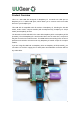
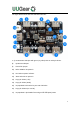
The figure below shows how the USB hub looks like:
1~7) Downstream USB port with green (or yellow) LED as activity indicator
8) Upstream USB port
9) Power link jumper
10) Micro-USB DC 5V power in
11) Red LED as power indicator
12) Alternative DC 5V power in
13) Pogo pin holder (+5V)
14) Pogo pin holder (GND)
15) Unpopulated 5x2 header for port state indication
16) Pogo pin holders (D+ and D-)
17) Unpopulated 2-pin header for turning on/off USB ports’ power