VTEC AIR FLOW CONVERTERⅡ WIRING DIAGRAM BY MODEL This document describes car models to which the VTEC Airflow Converter II (Product code: 401-A915/401-A815) is applicable, and ECU terminal arrangement drawings. For the operating method and precautions for the VTEC Airflow Converter II, refer to the Instruction Manual. For installing the VTEC Airflow Converter II, both this document and the Instruction Manual are required.
■Contents ■Introduction _____________________________________________________ P2 ■Precaution on Installation ______________________________________ P3 ■Installation ______________________________________________________ P5 ■ECU Arrangement Drawing _____________________________________ P10 ■How to Refer to the ECU Terminal Arrangement Drawing ____ P11 Table of Applicable Models.......................................................... P12 ECU Terminal Arrangement Drawing .....................................
■Precaution on Installation ●When installing this product, do not use any electro-tap in any case. Using the electro-tap makes the contact status unstable. Its contact defect may causes a malfunction to the product and damage to this product and the vehicle. Be sure to use the attached splice and dedicated tools such as cutting pliers for electric work to install the product securely. ●Insulate the metallic portion of the harness securely with a vinyl tape.
●The ground conductor of this product has two branches (black and brown). This has a very important significance to secure the voltage conversion accuracy. Connect the ground conductor by referring to the following figure. Installing the ground conductor in a different way from the connecting method specified by A’PEX will give damage to this product and the mounted car engine. Correct Connecting Method for the Ground Conductor Connect the ground conductor to two positions of the same line.
■Installation ●Connecting the VAFC II 1.Remove the negative (-) terminal of the battery. advice! There is some setting data on car audio, car navigation, etc. that is backed up by battery power supply. We recommend you to take a note of the data beforehand lest they should be lost. ! CAUTION ●Before starting the wiring work, remove the negative terminal of the battery. If not, a fire will be caused by short circuit, thereby giving damage to electric parts.
■Installation (cont.) ! CAUTION ●Be sure to connect the black wire and the brown wire of the harness attached to the VAFC II to the ground conductor. This product may not function normally, thereby giving damage to the product and the engine. ●When locating each wire, take special care not to cause a short circuit. A fire may be caused or electric devices may be damaged. ●Install the splice for branching securely without any contact defect. A fire may be caused or electric devices may be damaged. 4.
■Installation (cont.
! WARNING ●Install the V-AFC II so that it may not interfere with driving. Normal driving operations may be prevented, resulting in an accident. ●Do not install the V-AFC II in a high-temperature place or a place exposed to direct water. An electric shock or fire may be caused or electric parts may be damaged. A malfunction may be caused, thereby giving damage to the vehicle. ●When passing the connecting harness of the V-AFC II, arrange the harness so as not to touch the moving portion.
! CAUTION ●Do not start the engine in any case before the initial setup is performed. If the engine is started without initial setup, the engine may be damaged. Set the corresponding items by referring to page 13 in the Chapter pertaining to “Initial Setup” in the separate Instruction Manual with regard to the initial setup method. ! WARNING ●When the engine warning lamp in the meter comes on, you must ask the distributor of the model for inspection.
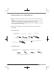
■ECU Arrangement Drawing ●Perform operations by referring to the symbols in the corresponding columns of the tables of applicable models on and after page 12.
■How to Refer to the ECU Terminal Arrangement Drawing This ECU terminal arrangement drawing is on the assumption that the connector is viewed from the direction of the arrow. The direction of the ECU varies depending on each vehicle. Perform the installation work after confirming the connector shape and the number of pins carefully.
■Table of Applicable Models Car name Car model Engine model Manufacturing year S2000 AP1 F20C ‘99.4∼‘03.9 ※Excluding VTEC 3 cars ECU position A Remarks Type R※1 (220ps) DC5 INTEGRA (including the ’98 specification) K20A ‘01.7∼‘03.8 D ‘95.9∼‘01.6 DC2 DB8 B18C DA8 DA6 B16A ‘89.4∼‘93.5 EP3 K20A ‘01.12∼※ H6-a 1 1 H7-a iS ※1 3 160ps ※2 H7-b M/T H4-a A/T H2-c M/T H3-a A/T H2-b C D17A EU2 EU1 D15B ‘00.10∼‘03.
Car name CR-X Car model Engine model EG2 B16A EG1 EF8 Manufacturing year ECU position ‘92.3∼‘95.10 A Remarks Terminal drawing Sensor type 1 H3-a D15B B16A VTEC No. 2 ‘89.9∼‘92.2 C H1-a 1 BB8 ‘96.12∼‘00.9 H4-a BB6 PRELUDE H22A BB4 BB1 ACCORD EURO R C ‘91.9∼‘96.11 CL1 H22A ‘00.6∼‘02.9 CL9 K24A ‘02.12∼※ H3-a With TRC H2-a E M/T ‘00.6∼‘02.9 CL3 Without TRC 1 H6-a 1 H9-c 1 H6-a A/T H5-a CF5 ACCORD F20B E M/T H6-a ‘97.9∼‘02.
Car name Car model Engine model Manufacturing year ECU position TORNEO EURO R CL1 H22A ‘00.6∼‘02.9 E M/T ‘00.6∼‘02.9 CL3 Remarks Terminal drawing Vehicle No. H6-a 1 Sensor type H6-a A/T H5-a CF5 F20B E TORNEO ‘97.9∼‘02.9 CF4 3 M/T PR-6 H6-a A/T H5-a LAGREAT CF3 F18B RL1 J35A ‘99.6∼‘04.4 E RB2 RB1 K24A ‘03.10∼※ B RA9 RA8 J30A ‘00.1∼‘03.9 160ps H5-b 2 H9-d 3 H5-b 2 H5-a 3 H4-b 2 H5-a 3 H9-a 3 PR-11 ※1 E ODYSSEY STEP WAGON RA7 RA6 F23A ‘99.12∼‘03.
■ECU Terminal Arrangement Drawing IG power VTEC solenoid signal IG power Ground VTEC solenoid signal rpm Throttle signal rpm Ground VTEC solenoid signal rpm Pressure signal VTM signal Pressure signal Throttle signal VTM signal ※It is not necessary to wire for the vehicle without the VTM signal IG power Ground IG power rpm VTEC solenoid signal Pressure signal VTM signal Throttle signal Pressure signal Throttle signal Ground ※There might not be free space of connector rpm Ground
※It is not necessary to wire for the vehicle without the VTM signal IG power VTC cam signal IG power VTEC Ground Throttle signal solenoid signal Pressure signal TDC signal VTEC Ground Throttle signal solenoid signal VTC cam signal TDC signal IG power Ground Pressure signal Pressure signal IG power Ground Throttle signal VTC cam signal Throttle signal 16 TDC signal Ground VTM rpm VTEC solenoid signal Throttle signal IG power rpm rpm VTEC solenoid signal Pressure signal rpm VTEC
※It is not necessary to wire for the vehicle without the VTM signal H9-c IG power Ground Throttle signal TDC signal VTC cam signal VTEC solenoid signal rpm Pressure signal H9-d IG power VTEC solenoid signal Ground Throttle signal TDC signal VTC cam signal Pressure signal rpm 17
Notes 1. The contents of this document are subject to change without previous notice. 2. The contents of this document have been prepared with extreme care. However, if you find a doubt, error, or other fault, inform us of it. 3. A part or all of this document may not be reproduced in any form without prior written permission, and also may not used without the prior written permission of APEXERA CO., LTD. under the copyright except for private use.