F220 F110/110 The VAC Phi Two Twenty Monophonic Beam Power Amplifier & Phi 110/110 Stereo Beam Power Amplifier Operation & Maintenance Information Valve Amplification Company Manual issued 01/24/2004 Revised 07/02/2004
PLEASE READ CAREFULLY Your Phi Beam Power amplifier is fitted with a unique output tube monitoring circuit. Rather than directly contacting the audio path, and thus contaminating the pure sound, the temperature of a small cathode resistance is sensed. The four bi-color LED’s on the front panel indicate the tubes’ conditions. If the idle current of a KT88 output tube drops below nominal limits, the LED corresponding to that tube will light green.
CAUTION THE AMPLIFIER AND POWER SUPPLY CONTAIN NO USER SERVICEABLE PARTS. DO NOT REMOVE THE BOTTOM PLATES OR CHASSIS COVERS. LETHAL VOLTAGES ARE PRESENT WITHIN THE CHASSIS. DO NOT OPERATE THE UNITS IF THEY ARE WET. VACUUM TUBES BECOME HOT ENOUGH TO CAUSE SERIOUS BURNS. NEVER TOUCH A TUBE WHEN THE UNIT IS ON. IT MAY TAKE SEVERAL MINUTES FOR THE TUBES TO COOL DOWN AFTER THE UNIT IS SWITCHED OFF. IT IS STRONGLY RECOMMENDED THAT THE TUBE COVERS BE LEFT IN PLACE AT ALL TIMES.
INTRODUCTION The Phi Beam Power amplifiers are unique power amplifiers, and the most power and detailed in VAC’s history. Excellent linearity is achieved without resorting to loop negative feedback, for a more natural, dimensional sound. A total of four KT88 are used in Class A1. Uniquely, each is provided with a separate DC heater supply to ensure that no undesirable couplings occur; only the intended ideal signal path exists.
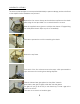
UNPACKING & ASSEMBLY The vacuum tubes and glass covers are packed individually to prevent damage, and must be fitted to the amplifier before installation can proceed. Remove the four screws that secure the aluminum top frame to the chassis pillars using the tool provided. Turn counterclockwise to remove. Wear the supplied cotton gloves to minimize the chance of fingerprinting the nickel plated chassis. Wipe any oils off immediately. Take care to prevent the tool from scratching the chassis.
The front glass has the etched VAC logo. Install this between the front pillars. Take great care not to scratch this glass. The front glass fits into a small channel in the front plate. Tighten the white nylon setscrews that secure the rear glass and side glasses. Turn clockwise to tighten. There are four setscrews for each glass plate. Do not tighten the setscrews for the front glass yet. Install the six aluminum blocks at the top of the rear glass and side glasses.
Tighten the four white nylon setscrews that secure the front glass using the tool provided. Turn clockwise to tighten. Do not over tighten. Install the vacuum tubes. Each tube or its box has a “V” number, which corresponds to the labels on the top plate of the amplifier; these indicate where each tube should be installed. Fit each tube into the matching socket, first removing any sticker from the amplifier and/or the tube.
INSTALLATION 01) 02) 03) Attach the cord from the power supply to the amplifier and screw the connector collar down fully; this takes many turns. Connect the speaker cables; the black lead goes to “-“ or “Ground”. The red lead goes to “+” or “Positive”. The speaker impedance selector switch should be set to match your loudspeakers. Set the input type switch to XLR (and RCA isolated) or RCA direct.
INPUT CONNECTORS XLR connection, balanced or single-ended, are made to the XLR jack on the rear panel. The INPUT SELECT toggle switch is set to the BALANCED position. The XLR connection follows the EIA “pin 2 hot” polarity convention. RCA (single ended) connection normally is made to the RCA jack on the rear panel. This is the “direct in” mode.
OPERATION By time delay, sound will begin approximately 60 seconds after turn on. As with all high fidelity products, the sound characteristic of the VAC changes somewhat as it warms up. Best sound will be achieved after about one hour of operation. We advise against leaving the equipment on at all times for safety reasons (see Safety Notice at the front of this manual), and because of the attendant acceleration of output tube wear and power consumption.
FEEDBACK Your Phi is equipped with variable negative feedback, controlled by a toggle switch on the rear panel. The switch has two positions: zero feedback, and 12 dB of overall negative feedback. With many loudspeakers, the best overall sound will be attained with zero feedback. Some speakers have significant variations of impedance with frequency; such speakers may sound better when feedback is selected. Think of feedback as being like a spice, and “season to taste.
INSTALLING NEW OUTPUT TUBES Output tubes are type KT88. Replacement output tubes should be purchased from VAC. It is important that the tubes be checked for any tendency to mechanical or electrical shorts (see Safety Notice at the front of this manual). It is desirable that tubes be in matched quartets for each channel, and be close to the "bogey" values for the major parameters. Make certain that each tube fits firmly in its socket. ALL POWER MUST BE OFF.
CHECKING OUTPUT TUBE CONDITION As described at the beginning of this manual, the Phi is equipped with the KT88 Sentry circuit, which continuously monitors each output tube to ensure that it is operating within normal limits. Each tube has a corresponding indicator light on the front panel. A green indicator light will be seen as the amplifier warms up, or when a tube’s idle current is less than normal.
REPLACEMENT OF LOW LEVEL TUBES All power must be switched off. Allow tubes to cool down. Remove the top glass cover. Remove and replace with new tubes of the appropriate types, noting the location of holes in the socket and pins of the tubes. Replace the glass cover before operating the amplifier. Replacement tubes are available from VAC and other sources. For further information, refer to Tips & Advice: A Word About Tubes in General and Tips & Advice: A Word About Low Level Tubes.
TIPS & ADVICE SECTION A Word About Tubes in General It is true that each brand of tube sounds different in a particular high resolution circuit. This is because no two manufacturers make a tube type in quite the same way, and the central tendencies of the performance parameters will differ slightly with each maker. To emphasize the point, examine the plate structure of any two 6SN7 from different manufacturers will probably find that they may not even the same shape and size.
Tips: Output Tubes Your VAC Amplifier uses the KT88 kinkless tetrode. It is strongly recommended that replacement tubes be purchased only from VAC. If, however, you want to customize the sound to your tastes, be aware that as with interconnects and speaker cables, each tube manufacturer's KT88 tends to have a distinct sound, as well as its own reliability profile. Tips: Low Level Tubes The Voltage Amplifier/Phase Splitter and driver tubes in the Phi is the 6SN7 medium mu octal twin triode.
Tips: Impedance Matching We strongly suggest that you experiment with the three available impedance connections for the best sonic match with your system. Since no loudspeaker represents an unchanging impedance at all frequencies, it is impossible to assert with certainty which output tap is appropriate to use. In many systems an amazing difference in sound will exist between the various impedance taps.
Tips: Audio Grounding Systems incorporating single-ended interconnect cables (“RCA cables”) are prone to a problem known as “ground looping”, which can result in extraneous hums and buzzes audible through the loudspeaker. If this occurs in your system, you have two options: 1) to work to minimize the ground loop, or 2) use the balanced input via the supplied adapter to break the ground loop.
SPECIFICATIONS The VAC Phi has been developed with the critical ear as the major arbiter of quality, with both conventional and unique measurements providing insight and guidance as necessary. The lack of emphasis on measurements is due to the fact that engineering's arsenal of equipment and techniques do not operate on the pattern recognition principals that control human perception of sound. In the immortal words of Daniel von Recklinghausen, if it measures good and sounds bad, it is bad.
WARRANTY Your equipment is warranted for a period of thirty (30) days from the date of purchase. In addition, if the registration form is received by VAC along with a copy of your sales receipt from an authorized VAC dealer within this thirty days, a service contract will be extended to cover your equipment for three (3) years (tubes excepted). This warranty applies only to units sold in the United States of America through authorized VAC dealers. It covers factory service and standard return shipping.