
User Manual


page 41 of 51
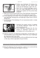
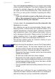
➨ Position new diaphragm (F) between dia-
phragm clamping disc with square head
screw (E) and diaphragm support disc (G).
+ Note: This is a double diaphragm consist-
ing of two single diaphragms! Put the two
diaphragms together with the printed sides
outwards.
+ Make sure that the square head screw of the diaphragm clamping disc
is correctly seated in the guide hole of the diaphragm support disc.
➨ Lift the diaphragm at the side. Place the diaphragm carefully together
with diaphragm clamping disc and diaphragm support disc in the dia-
phragm key.
+ Avoid damage of the diaphragm: Do not excessively bend or crease
the diaphragm.
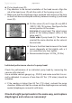
E
G
F
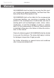
+ Assemble the original number of washers
(H) between diaphragm support disc (G)
and connecting rod (I).
➨ Screw diaphragm clamping disc (E), dia-
phragm (F), diaphragm support disc (G),
and washers (H) to connecting rod (I).
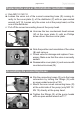
➨ Optimum torque for the diaphragm support disc: 4.4 ft
.
lb
f
(6 Nm), it is
recommended to use a torque wrench. Attach Allen key to diaphragm
key (hexagonal bolt 6 mm wide).
Note: Never use the diaphragm key with any additional tools like tongs
or Allen keys without appropriate torque limitation.
F
E
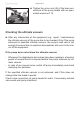
Assembling the pump heads
➨ Bring the diaphragm (F) into a position, in which it is in contact with the
housing (J) and centered with respect to the bore.