
User Manual


page 42 of 51
(1)
(2)
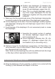
➨ Put on head cover (D).
+ Pay attention to the correct orientation of the head covers: Align the
nib at the head cover (D) with the notch of the housing cover (A).
+ Make sure that the diaphragm stays centered with respect to the bore
so that it will become clamped uniformly between housing (J) and head
cover (D).
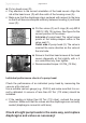
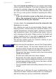
➨ Put the valves (C) an O-rings (B, only MD 8
/ MD 12 / MV 10) in place. See gure for the
correct position of the valves:
Inlet side of pump head: The valve tongue
points at the kidney-shaped orice in the
valve seat (1).
Outlet side of pump head (2): The valve is
oriented the same direction as the valve at
the inlet side.
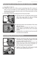
➨ Screw in the Allen head screws at the head
covers diagonally at rst slightly with a 5
mm wide Allen key, then tighten.
+ Recommended torque: 8.9 ft
.
lb
f
(12 Nm).
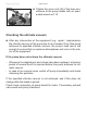
Individual performance check of a pump head:
Check the performance of an individual pump head by measuring the
vacuum at its inlet port.
Use a suitable vacuum gauge (e.g., DVR 2) and make sure that it is cor-
rectly calibrated. A vacuum of less than 82 Torr (110 mbar) should be
indicated.
+ If the reading is higher than 82 Torr (110 mbar), recheck the pump
chamber. Make sure that the valves and the diaphragms are correctly
seated (diaphragms concentric with bore).
Check all eight pump heads in the same way, and replace
diaphragms and valves as necessary!