Part I page 1 of 120 Technology for Vacuum Systems Instructions for use Part I of II Part I: Safety information Technical data Use and operation PC 3001 VARIOpro PC 3001 TE VARIOpro PC 3001 VARIOpro IK PC 3001 VARIOpro EK Peltronic Chemistry pumping unit with speed control
page 2 of 120 Dear customer, Your VACUUBRAND diaphragm pumps are designed to provide you with many years of trouble-free service with optimal performance. Our many years of practical experience allow us to provide a wealth of application and safety information. Please read these instructions for use before the initial operation of your pump.
page 3 of 120 DE Achtung: Die vorliegende Betriebsanleitung ist nicht in allen EU-Sprachen verfügbar. Der Anwender darf die beschriebenen Geräte nur dann in Betrieb nehmen, wenn er die vorliegende Anleitung versteht oder eine fachlich korrekte Übersetzung der vollständigen Anleitung vorliegen hat. Die Betriebsanleitung muss vor Inbetriebnahme der Geräte vollständig gelesen und verstanden werden, und alle geforderten Maßnahmen müssen eingehalten werden.
page 4 of 120 DA Bemærk: Denne manual foreligger ikke på alle EU sprog. Brugeren må ikke betjene apparatet hvis manualen ikke er forstået. I det tilfælde skal en teknisk korrekt oversættelse af hele manual stilles til rådighed. Manual skal være gennemlæst og forstået før apparatet betjenes og alle nødvendige forholdsregler skal tages. »Sikkerhedsregler for vakuumudstyr« EE Tähelepanu! Käesolev kasutusjuhend ei ole kõigis EL keeltes saadaval.
page 5 of 120 HU Figyelem! Ez a kezelési utasítás nem áll rendelkezésre az EU összes nyelvén. Ha a felhasználó nem érti jelen használati utasítás szövegét, nem üzemeltetheti a készüléket. Ez esetben a teljes gépkönyv fordításáról gondoskodni kell. Üzembe helyezés előtt a kezelőnek végig kell olvasnia, meg kell értenie azt, továbbá az üzemeltetéshez szükséges összes mérést el kell végeznie.
page 6 of 120 NL Attentie: Deze gebruiksaanwijzing is niet in alle talen van de EU verkrijgbaar. De gebruiker moet niet met dit apparaat gaan werken als voor hem/haar de gebruiksaanwijzing niet voldoende duidelijk is. Bij gebruik van deze apparatuur is het noodzakelijk een technisch correcte vertaling van de complete gebruiksaanwijzing te hebben. Voor het in gebruik nemen van het apparaat moet de gebruiksaanwijzing volledig gelezen en duidelijk zijn en dienen alle benodigde maatregelen te zijn genomen.
page 7 of 120 SE Varning: Denna instruktion är inte tillgänglig på alla språk inom EU. Användaren får inte starta utrustningen om hon/han inte förstår denna instruktion. Om så är fallet måste en tekniskt korrekt instruktion göras tillgänglig. Instruktionen måste läsas och förstås helt före utrustningen tas i drift och nödvändiga åtgärder göres. ”Säkerhetsinformation för vakuumutrustning” SI Pozor: Ta navodila niso na voljo v vseh jezikih EU. Uporabnik ne sme upravljati z napravo, če ne razume teh navodil.
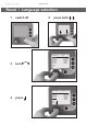
page 8 of 120 Reset / Language selection 1 switch off 2 press both C VC 3000 3 turn D eutsch English Français Italiano Español Türkçe 한국어 中文 C V C 3000 4 press D eutsch E nglish Français Italiano E spañol Türkçe 한국어 中文 V 2.0 Portuguê Ρyccкий Polski N ederl. 日本語 Suomi V 2.0 Portuguê Ρyccкий Polski N ederl.
page 9 of 120 Contents Part I................................................................. 1 Reset / Language selection.............................................. 8 Safety information!............................................................ 11 Important information!.........................................................................11 General information............................................................................ 13 Intended use.............................................
page 10 of 120 VACUULAN function......................................................... 69 Application examples....................................................... 71 Vacuum for filtration and suction....................................................... 71 Vacuum for gel dryer, drying chambers and vacuum concentrators.................................... 72 Vacuum for distillation and evaporation (e.g., rotary evaporator) 72 Vacuum for VACUU•LAN networks............................................
page 11 of 120 Safety information! Important information! + Keep this manual complete and accessible to personnel at all times! + Read this manual carefully before installing or operating the equipment. Observe the instructions contained in this manual. PC 3001 VARIOpro with Peltronic emission condenser: Read the manual of the emission condenser Peltronic as well and observe likewise the instructions contained in that manual. + Do not modify the equipment without authorization.
page 12 of 120 ➨ DANGER indicates a hazardous situation which, if not avoided, will result in death or serious injury. + WARNING indicates a hazardous situation which, if not avoided, could result in death or serious injury. NOTICE • CAUTION indicates a hazardous situation which, if not avoided, could result in minor or moderate injury. NOTICE is used to address practices not related to personal injury. Caution! Hot surface! Disconnect equipment from AC power.
page 13 of 120 General information NOTICE Remove all packing material from the packing box. Remove the product from its packing box and retain all packaging until the equipment is inspected and tested. Remove the protective caps from the inlet and outlet ports and retain for future use. Inspect the equipment promptly and carefully. If the equipment is damaged, notify the supplier and the carrier in writing within three days. Retain all packing material for inspection.
page 14 of 120 ☞ Comply with all notes on correct vacuum and electrical connections; see section „Use and operation“, pg. 38. + Do not use the pump to generate pressure. + The pumps are designed for ambient temperatures during operation between +50°F and +104°F (+10°C and +40°C). Periodically check maximum temperatures if installing the pump in a cabinet or a housing. Make sure ventilation is adequate to maintain recommended operating temperature.
page 15 of 120 The supply cable may be fitted with a molded European IEC plug or a plug suitable for your local electrical supply. The cable contains wires color coded as follows: green or green and yellow: ground; blue or white: neutral; brown or black: hot. ☞ Due to the high compression ratio, the pump may generate overpressure at the outlet. Check pressure compatibility with system components (e.g., exhaust pipeline or exhaust valve) at the outlet. ☞ Do not permit any uncontrolled pressurizing.
page 16 of 120 • Ensure that no foreign objects can be drawn into the pump. • Check the power source and the pump’s rating plate to be sure that the power source and the equipment match in voltage, phase, and frequency. • Ensure that the coolant outlet pipe is always free and that it cannot get blocked. If installing an optional coolant valve, it must always be in the supply line of the exhaust waste vapor condenser. NOTICE Make sure ventilation is adequate to maintain recommended operating temperature.
page 17 of 120 Ambient conditions ➨ Do not reach for this product if it has fallen into liquid. There is a risk of deadly electrical shock. Unplug the system immediately. + Do not use this product in an area where it can fall or be pulled into water or other liquids. • Adopt suitable measures in case of differences from recommended conditions, e.g., using the equipment outdoors, installation in higher altitudes, conductive pollution or external condensation on the pump.
page 18 of 120 mospheres (see section „` Important information: Equipment marking (ATEX)“, pg. 25). ➨ The pumps are not suitable to pump any of the substances listed below. Do not pump: - unstable substances - substances which react explosively under impact (mechanical stress) without air - substances which react explosively when being exposed to elevated temperatures without air, - substances subject to auto-ignition, - substances which are inflammable without air - explosive substances.
page 19 of 120 reactions of the pumped substances with each other and with the pump’s materials. Safety during operation ➨ Adopt suitable measures to prevent the release of dangerous, toxic, explosive, corrosive, noxious or polluting fluids, vapors and gases. To prevent any emission of such substances from the pump outlet, install an appropriate collecting and disposal system and take protective action for pump and environment.
page 20 of 120 ☞ Attention: At pressures above approximately 795 Torr (1060 mbar) the pressure reading becomes incorrect due to saturation of the pressure transducer. The display flashes. Release pressure immediately! Risk of bursting! + Comply with applicable regulations when disposing of chemicals. Take into consideration that chemicals may be contaminated. Take adequate precautions to protect people from the effects of dangerous substances (chemicals, thermal decomposition products of fluoroelastomers).
page 21 of 120 ☞ Do not overfill the condenser. Lowest permissible coolant temperature: -112°F (-80°C). ☞ Maximum operating pressure: 16 psi (1.1 bar) absolute. • Ensure that no parts of your clothing, hair or fingers can be caught or drawn in at the inlet of the pump. Never insert fingers or drop any other object into the inlet or outlet. • Pumping at high inlet pressure may lead to overpressure at the gas ballast valve. Pumped gases or condensate might be expelled if the valve is open.
page 22 of 120 PC 3001 TE VARIOpro: • Comply with all applicable safety measures and requirements when using cryogenic coolants (e.g., dry ice). Attention: Coolant media may cause severe frostbite when coming in contact with skin! • Prior to every use: Inspect the condenser for faults. There must be no damage on the glass surface. Do not use damaged components. • Use only transport receptacles intended for coolants. • Wear safety glasses and protective gloves.
page 23 of 120 Maintenance and repair NOTICE In order to comply with laws (occupational, health and safety regulations, safety at work law and regulations for environmental protection) vacuum pumps, components and measuring instruments can only be returned when certain procedures (see section „Notes on return to the factory“, pg. 113) are followed. Take advantage of our service seminars, which put special focus on the maintenance and repair of vacuum pumps.
page 24 of 120 the pump and other components from the vacuum system. Allow sufficient cooling of the pump. Separate the pump from the coolant circuit and drain condensate, if applicable. NOTICE Ensure that maintenance is done only by suitably trained and supervised technicians. Ensure that the maintenance technician is familiar with the safety procedures which relate to the products processed by the pumping system. Only dismantle the pump as far as necessary.
page 25 of 120 ` Important information: Equipment marking (ATEX) VACUUBRAND equipment bearing mark (see rating plate) ` II 3G IIC T3 X Internal Atm. only Tech. File Ref.: VAC-EX01 The classification II 3G IIC T3 X according to ATEX is only valid for the inner part (wetted part, pumped gas or vapor) of the equipment. The equipment is not suitable for use in external, potentially explosive atmospheres (environment). The overall category of the equipment depends on the connected components.
page 26 of 120 • The equipment is designated for an ambient and gas inlet temperature during operation of +10 to +40°C. Never exceed these ambient and gas inlet temperatures. If pumping / measuring gases which are not potentially explosive, extended gas inlet temperatures are permissible. See instructions for use, section “Gas inlet temperatures” or “Technical data”. After any intervention at the equipment (e.g., repair / maintenance) the ultimate vacuum of the pump has to be checked.
page 27 of 120 Technical data General technical data valid for all pumping units Maximum pumping speed (ISO 21360) cfm (m3/h) 1.2 (2.0) Ultimate vacuum (absolute) without gas ballast* Torr (mbar) 1.5 (2) Ultimate vacuum (absolute) with gas ballast* Torr (mbar) 3 (4) Maximum permissible inlet and outlet pressure (absolute) psi (bar) 16 (1.1) Maximum permissible pressure difference between inlet and outlet psi (bar) 16 (1.
page 28 of 120 Type PC 3001 VARIOpro PC 3001 VARIOpro IK Inlet hose nozzle for tubing I.D. 1/4” / 3/8” (hose nozzle DN 6/10 mm) hose nozzle for tubing I.D. 1/2” (hose nozzle DN 13 mm) hose nozzle for tubing I.D. 3/8” (hose nozzle DN 10 mm)**** Outlet Coolant connection (waste vapor condenser) hose nozzle for tubing I.D.
page 29 of 120 Controller CVC 3000 Pressure transducer Display ceramic diaphragm (alumina), capacitive, absolute pressure, gas type independent LCD graphic display, illuminated Pressure units / scale (selectable) Torr, mbar or hPa Measuring range (absolute) 810 - 0.1 Torr (1080 - 0.1 mbar) Maximum control range with internal pressure transducer (absolute)* 795 - 0.1 Torr (1060 - 0.1 mbar) Resolution 0.07 Torr (0.
page 30 of 120 Gas inlet temperatures Permitted range of gas temperatures at inlet > 75 Torr (100 mbar) ➨ 50 °F to 104 °F Continuous operation (high gas load) (+10°C to +40°C) < 75 Torr (100 mbar) ➨ 32 °F to 140 °F* Continuous operation (low gas load) (0°C to +60°C*) Short-time < 75 Torr (100 mbar) ➨ 14 °F to 176 °F* (< 5 minutes) (low gas load) (-10°C to +80°C*) * if pumping potentially explosive atmospheres: 50 °F to 104 °F (+10°C to +40°C) Operating condition Inlet pressure Wetted parts Components Pum
page 31 of 120 Abbreviations EK: ETFE: ECTFE: FFKM: FPM: IK: PA: PBT: PET: PP: PPS: PTFE: PVF: TE: Waste vapor condenser (emission condenser) Ethylene/Tetrafluoroethylene Ethylene/Chlorotrifluoroethylene Perfluoro elastomer Fluoroelastomer Waste vapor condenser (inlet condenser) Polyamide Polybutylene terephthalate Polyethylene terephthalate Polypropylene Polyphenylene sulfide Polytetrafluoroethylene Polyvinyl fluoride Dry ice waste vapor condenser Pump parts Position Component Position Componen
page 32 of 120 PC 3001 VARIOpro 6 12 11 8 7 9 1 14 5 17 10 2 4 3
page 33 of 120 PC 3001 TE VARIOpro 13 6 7 8 1 17 5 14 10 2 4 3
page 34 of 120 PC 3001 VARIOpro IK 6 12 8 7 11 12 1 11 15 9 5 17 10 2 4 3
page 35 of 120 PC 3001 VARIOpro emission condenser Peltronic 5 16 8 6 7 4 1 3 Netzschalter Kaltgerätebuchse 4 3 2 10
page 36 of 120 PC 3001 VARIOpro (without exhaust waste vapor condenser) 7 8 6 with silencer 1 14 5 2 4 3 10
page 37 of 120 Rear side CVC 3000 jacks for connection of VACUU•BUS components (e.g.
page 38 of 120 Use and operation When switching on the controller CVC 3000 for the very first time, a menu to select the language of the controller menu is displayed. Select the desired language (e.g., ”English”) by turning the selection knob and press to confirm. Then select the pressure unit (”mbar”, ”Torr” or ”hPa”) in the same way. It is possible to access the language selection menu at any time by switching on the controller while keeping the selection knob pressed.
page 39 of 120 + Make sure ventilation is adequate, especially if the pump is installed in an enclosure, or if the ambient temperature is elevated. Provide external ventilation, if necessary. • Reduce the transmission of vibration. Prevent mechanical load due to rigid pipelines. Insert elastic hoses or flexible elements as couplings between the pump and rigid pipes. Note: Flexible elements will compress or flatten when evacuated if not designed for use under vacuum.
page 40 of 120 Use a suitable valve to isolate the pump from the vacuum application. This is to allow the pump to warm up before pumping condensable vapors and to clean the pump after use before it is switched off. When assembling, ensure vacuum-tightness. After assembly, check the whole system for leaks. Secure hose connections at the pump appropriately, e.g., with hose clamps, to protect against accidental detachment.
page 41 of 120 measurement connection at CVC 3000 - Condensate and deposits will affect the measurement results. Clean the pressure transducer, if necessary. See section „Cleaning the pressure transducer“, pg. 83. Connecting components at the controller: At the rear side of the controller are connections for e.g., an optional coolant valve and/or an external pressure transducer and/or an external venting valve, as well as a venting connection and the serial interface RS 232C.
page 42 of 120 catchpot at the inlet (10) catchpot at the outlet (10) 6 12 11 Catchpots: The catchpot at the inlet protects against droplets and particles from entering the pump. ☞ Enhances lifetimes of diaphragms and valves. ☞ Improves vacuum performance in applications with condensable vapors. Both catchpots are coated with a protective layer to protect against shattering in case of breakage or implosion. ➨ Assemble the catchpots at the inlet and at the outlet using joint clips.
page 43 of 120 ➨ Prevent the discharge of dangerous gases and vapors to the surrounding atmosphere. If appropriate, connect the exhaust line to a suitable treatment system. + Never block the gas outlet ((8) hose nozzle for tubing I.D. 3/8” (10 mm)). The exhaust hose has always to be unobstructed and without back pressure to enable an unhindered discharge of gases and protect the pump valves from damage.
page 44 of 120 ➨ Adopt suitable measures to prevent the formation of explosive or flammable mixtures, use inert gas for venting if necessary. ➨ Prevent the discharge of dangerous gases and vapors to the surrounding atmosphere. If appropriate, connect the exhaust line to a suitable treatment system. ➨ Adopt suitable measures to prevent the release of dangerous, toxic, explosive, corrosive, noxious or polluting fluids, vapors and gases when disposing of condensates.
page 45 of 120 NOTICE Use the equipment only as intended, that is, for condensation of vapors at the pump outlet or inlet. Suitable coolants: e.g., dry ice or ethanol-dry ice mixture or water-ice mixture. cap inner part of condenser ➨ Remove cap. Fill coolant into the coolant chamber. Put cap back in place. Do not clamp the cap. ☞ Check coolant level at appropriate intervals. ➨ Check level of condensate at appropriate intervals and drain condensate if necessary.
page 46 of 120 • Ensure that the coolant outlet tubing at both condensers is always unobstructed and that it cannot get blocked.
page 47 of 120 During operation ➨ Vent and dispose of potentially dangerous gases or vapors at the outlet of the pump appropriately. + Due to the high compression ratio, the pump might generate overpressure at the outlet. Check pressure compatibility with system components (e.g., exhaust tubing or exhaust valve) at the outlet. Ensure that the pump outlet is neither blocked nor restricted.
page 48 of 120 Clean the pump if necessary to avoid an increase of the pump’s operating temperature. Operation with silencer (optional) at the outlet: Operating the pump at a high inlet pressure or pumping dusty gases for a long time may cause clogging of the silencer. Check the silencer regularly and replace if necessary. A temperature sensor at the circuit board protects the motor: Current limitation in the event the temperature at the circuit board raises above 158°F (70°C).
page 49 of 120 + Make sure that air/gas intake through the gas ballast valve can never lead to hazardous, explosive or otherwise dangerous mixtures. If in doubt, use inert gas. NOTICE To reduce condensation in the pump, do not pump vapor before the pump has reached its operating temperature. Open the gas ballast valve when pumping condensable vapors. Turn gas ballast cap to open valve. For condensable vapors (water vapor, solvents, etc.
page 50 of 120 exhaust waste vapor condenser (9) regularly; replace if necessary. Check especially for deterioration, coalescence and cracks. • Ensure that the coolant outlet hose is always free and that it cannot get blocked. • Maximum permissible coolant pressure at the exhaust waste vapor condenser: 87 psi (6 bar) absolute • Comply with the maximum permissible coolant pressures of additional components in the coolant circuit (e.g., coolant valve).
page 51 of 120 Catchpot at outlet: Remove joint clip. Remove catchpot and drain condensate. Catchpot at inlet: Admit air or inert gas (via the pump inlet) to restore atmospheric pressure in the catchpot before attempting removal. Remove joint clip. Remove catchpot and drain condensate. NOTICE Reattach drained catchpots. ☞ Important: Comply with regulations when disposing of solvents/condensates. Recycle if possible; purify if contaminated. Shutdown & storage The pump can be switched off under vacuum.
page 52 of 120 CVC 3000 Vacuum controller When switching on the CVC 3000 controller for the very first time, a menu to select the language of the controller menu is displayed. Select the desired language, e.g., ”English” by turning the selection knob and pressing to confirm. Then select the pressure unit (”mbar”, ”Torr” or ”hPa”) in the same way. It is possible to access the language selection menu at any time by switching on the controller while keeping the selection knob pressed.
page 53 of 120 Selection knob • • • • • Press to reach the set-up menu of the function Turn to choose the parameter you want to modify Press to select the parameter you want to modify Turn to change the set value of the parameter Press to confirm change of value and to reach further parameters, or to leave the set-up menu Display and symbols Vac control 100 1013.
page 54 of 120 100 Vacuum control to a preset vacuum value (here: 100 mbar/Torr/hPa); (without / with VACUU•BUS100 compatible VARIO pump) Actual pressure is in the range ”Set vacuum + hysteresis” (without VACUU•BUS-compatible VARIO pump) / Actual pressure = ”Set vacuum” (with VACUU•BUS-compatible VARIO pump) Flashing: The actual pressure is greater than the preset maximum value (“Maximum“) Minimum value (“Minimum“) reached 00:00:00 Process runtime (only if process control is running) Pump down (continuo
page 55 of 120 Notes on selecting the function The CVC 3000 controller can be adapted to the specific application by choosing the appropriate function depending on the connected components and the requirements of the application. Automatic detection of the components When switching on the controller, the configuration of the connected components is checked automatically. Connected components (e.g.
page 56 of 120 ”Vac control” • With pressure preselection, controls a VACUU•BUS-compatible VARIO pump to maintain pinpoint control of that pressure. • Coolant valve ”Auto mode” • Provides fully automatic boiling point determination and adaptation with pinpoint precision, and optimization of pumping speed with VACUU•BUS-compatible VARIO pumps. • Coolant valve ’’Program’’ • Control pump based on time and pressure preselections, or ”Auto mode”.
page 57 of 120 Menu guide Pump down Pump down * MODE Speed HI Minimum Off Delay Off Duration Off - - - - - - Graphic - - - - - - - - - - - - Back - - - - - - - 1013.2 mbar * Function Pump down Vac control Auto mode Program VACUULAN Configuration Configuration Adjustment 760 Torr RS-232... Sensors... Display... Autostart Off Defaults Cancel - - - - - - - Back - - - - - - - - - - - - - - - Back - - - - - - - * VACUULAN MODE 1013.
page 58 of 120 Vac control Vac control * MODE Set vacuum 75 Torr Speed HI Maximum Off Delay Off Duration Off - - - - - - Graphic - - - - - - - - - - - - Back - - - - - - - 1013.2 mbar Auto mode Sensitivity normal Speed HI Minimum Off Delay Off Duration Off - - - - - - Graphic - - - - - - - - - - - - Back - - - - - - - * Function Pump down Vac control Auto mode Program VACUULAN Configuration Auto mode MODE - - - - - - - - Back - - - - - - - 1013.2 mbar * Program MODE 1013.
page 59 of 120 Pump down function Function definition: ➨ Continuous pumping with pressure and time settings • Operation on demand of a speed controlled VACUU•BUScompatible VARIO pump Preselections ☞ Use the selection knob to select the parameters. All parameters can be altered even while operation control is running. ☞ Speed: Preselection of the motor speed for pump down. The selection ”HI” effects the maximum speed and best ultimate vacuum of the pump (with automatic speed reduction at ultimate vacuum).
page 60 of 120 ☞ If neither ”Minimum” nor ”Duration” is preset, process control has to be stopped by pressing key ”STOP”. The screen-shot shows the factory-set values. Pump down 760 Torr Pump down Speed HI Minimum Off Delay Off Duration Off - - - - - - Graphic - - - - - - - - - - - - Back - - - - - - - 10 mbar 00:03:50 When selecting ”Graphic” the display shows a pressure vs. time curve. The timeline in the diagram adapts automatically to the process time.
page 61 of 120 Vac Control function Function definition: ➨ Vacuum control to a preset vacuum value • Operation on demand of a speed controlled pump (VACUU•BUScompatible VARIO pump) Preselections + Use the selection knob to select the parameters. All parameters can be altered even while operation control is running. ☞ Set vacuum: The ”Set vacuum” is the set point for vacuum control with pinpoint precision for VACUU•BUS-compatible VARIO pumps.
page 62 of 120 A preset ”Duration” (process time) has no effect if the process is stopped due to a preset ”Maximum” before ”Duration” is reached. The ”Duration” is adjustable between 1-1440 minutes (24 h) or can be set to ”Off”. ”Off” means that no endpoint of the process is defined. The screen-shots show the factory-set values.
page 63 of 120 Alternatively: Fine tuning: The set vacuum can be fine-adjusted by turning the selection knob while process is running. + Turn the selection knob. + A full turn causes a change of the set vacuum of 9 Torr (12 mbar). + Turning the knob one detent causes a change of the set vacuum of 1 Torr (mbar).
page 64 of 120 Auto mode Function definition: ➨ Control of a VACUU•BUS-compatible VARIO pump in ”Auto mode”: Automatic detection of boiling points, and automatic adjustment of determined boiling points as process parameters change. Preselections ☞ Use the selection knob to set the parameters. ☞ Sensitivity: The ”Sensitivity” of the control determines the control speed. The ”Sensitivity” is adjustable to ”high”, ”normal” or ”low”. High sensitivity leads to a reduced pump-down speed, e.g.
page 65 of 120 ☞ Duration: ”Duration” determines the total process time since control start. The ”Duration” is adjustable between 1-1440 minutes (24 h) or can be set to ”Off”. A preset ”Duration” (process time) has no effect, if the process is stopped earlier by reaching the preset ”Minimum”. The screen-shot shows the factory-set values.
page 66 of 120 Program function Function definition: ➨ Permits ten programs to be defined and stored, each with up to ten program steps with preset values for vacuum and time. ➜ ☞ Edit: Use to define the preset values for the process run: Time: Defines either the process runtime for each program step to reach a preset vacuum level or, if programming a ”Step”, the runtime after having achieved the vacuum level. The total process runtime is shown in the base line.
page 67 of 120 Editing: + To select row: turn and press selection knob. + To adjust parameter: turn the selection knob. + To confirm parameter: Press selection knob. Controller will accept change and jump to the next parameter in the same row. + After 5 seconds without a change, the parameter is assumed to be the current setting. Select the next row to edit or return to the Program menu.
page 68 of 120 Attention: If the controller is set to ”Defaults”: ”On”, all stored programs will be deleted. Application example Example VACUU•BUS-compatible VARIO vacuum pump with speed control (e.g., with a rotary evaporator): Degassing and automatic distillation with timing Program No hh:mm:ss Vac Vent.
page 69 of 120 VACUULAN function Function definition: ➨ Optimizes vacuum control for vacuum networks (e.g., VACUUBRAND VACUU•LAN) ➨ Permits on-demand operation of a speed-controlled pump (VACUU•BUS-compatible VARIO pump) Preselections ☞ Use the selection knob to select the parameters. ☞ Set vacuum (the lower switch-off value): If the pressure drops below the ”Set vacuum”, a time-meter starts to run and the motor speed is reduced.
page 70 of 120 This screen-shot shows the factory-set values. VACUULAN 760 Torr Set vacuum 19 Torr Switch on 150 Torr Delay 15 min - - - - - - Graphic - - - - - - - - - - - - Back - - - - - - - VACUULAN 40 mbar 00:13:00 When selecting ”Graphic” the display shows a pressure vs. time curve. The timeline in the diagram adapts automatically to the process time. ☞ Press the selection knob twice to return to the standard display.
page 71 of 120 Application examples Assembly of a vacuum system ☞ Assemble the vacuum connection line between the vacuum pump and the vacuum application. + Assemble the vacuum connection line between the controller and the vacuum application, if the controller is not part of a pumping unit. ☞ Assemble electrical connections. ☞ Connect coolant if necessary. Vacuum for filtration and suction ☞ Select ”Pump down” function. ☞ If necessary, set value for ”Speed” (high or low pumping speed).
page 72 of 120 Vacuum for gel dryer, drying chambers and vacuum concentrators ☞ Select function ”Pump down” function. ”Speed” ”HI” is recommended. For gel dryers set a lower speed if necessary (if the gels tend to crack). ☞ Set ”Minimum” to prevent volatile components from evaporating. The process is stopped automatically as soon as ”Minimum” is reached. ☞ Set a process time (”Duration”) if necessary. ☞ Start process by pressing ”START/STOP” key.
page 73 of 120 ☞ When setting a value for ”Duration” the controller switches off the pump when ”Duration” has passed even if a preset ”Minimum” is still not reached. ☞ If neither ”Minimum” nor ”Duration” is preset, pumping down has to be finished by pressing the ”START/STOP” key. alternatively: Semi-automatic distillation and evaporation ☞ Select function ”Pump down”. ☞ Start process by pressing ”START/STOP” key. ☞ Observe process.
page 74 of 120 Vacuum for VACUU•LAN networks ☞ Select function ”VACUULAN”. ☞ Set ”Set vacuum” to a pressure which can be reached reliably in the vacuum network. Take account of the ultimate vacuum of the pump and of the system’s leak rate in case of no vacuum demand. ☞ Set ”Switch on” pressure appropriately to ensure sufficient vacuum for all connected applications. ☞ Set ”Delay” if necessary. ☞ Start process by pressing ”START/STOP” key.
page 75 of 120 Configuration In the ”Configuration” menu the device parameters are preselected. After 20 seconds without action the function ”Configuration” and its submenus (except submenu ”Sensors”) are quit automatically without storing any possibly changed parameter. Preselections ☞ Use the selection knob to select the parameters. ☞ Adjustment: Adjustment of the pressure transducer under vacuum and/or at atmospheric pressure, see also section „Readjustment of CVC 3000“, pg. 80.
page 76 of 120 Attention: If ”Autostart” is preselected, the process starts immediately after power failure without pressing any further key. It is the user’s responsibility to ensure that no dangerous status of the system due to the automatic startup can occur and to provide appropriate safety measures. If necessary, the user has to check prior to starting the process if the option ”Autostart” is enabled. + Defaults: If ”Defaults” is set to ”Load”, the controller is reset to factory set values.
Part II page 77 of 120 Technology for Vacuum Systems Instructions for use Part II of II PC 3001 VARIOpro Part II: PC 3001 TE VARIOpro Readjustment PC 3001 VARIOpro IK Interface parameters Accessories - Maintenance PC 3001 VARIOpro EK Peltronic Chemistry pumping unit with speed control
page 78 of 120 Contents Part I................................................................. 1 Reset / Language selection.............................................. 8 Safety information!............................................................ 11 Important information!.........................................................................11 General information............................................................................ 13 Intended use............................................
page 79 of 120 VACUULAN function......................................................... 69 Application examples....................................................... 71 Vacuum for filtration and suction....................................................... 71 Vacuum for gel dryer, drying chambers and vacuum concentrators.................................... 72 Vacuum for distillation and evaporation (e.g., rotary evaporator) 72 Vacuum for VACUU•LAN networks............................................
page 80 of 120 Readjustment of CVC 3000 NOTICE The vacuum gauge was adjusted using factory standards, which are traceable through regular calibration in an accredited laboratory (DAkkS calibration laboratory) to the German national pressure standard. Depending on the process and/or accuracy requirements, check the adjustment and readjust if necessary.
page 81 of 120 Adjustment under vacuum An adjustment under vacuum is only possible if the pressure is lower than 15 Torr (20 mbar) 0 mbar absolute. Evacuate the measurement connection of the CVC 3000 to a pressure < 0.1 Torr (mbar) (e.g. by applying a good two-stage rotary vane pump). ➨ In ”Configuration” menu, select program ”Adjustment” at the controller. ☞ The reading is automatically adjusted to ”zero”. ➨ Press the selection knob to confirm.
page 82 of 120 Calibration in the factory Control of measuring equipment The VACUUBRAND DAkkS calibration laboratory is accredited by the Deutsche Akkreditierungsstelle GmbH (national accreditation body of the Federal Republic of Germany) for the measurable variable pressure in the pressure range from 7.
page 83 of 120 Cleaning the pressure transducer ➨ Attention: Never use a pointed or sharp-edged tool to clean the pressure transducer. ➨ Never touch the ceramic diaphragm of the pressure transducer with hard objects. ➨ Fill the measurement chamber with a solvent (e.g., benzene) and allow sufficient cleaning time. Observe all regulations concerning usage and disposal of solvents! ➨ Drain the solvent and dispose of in accordance with regulations. Repeat cleaning if necessary.
page 84 of 120 Interface parameters The CVC 3000 controller is equipped with a serial interface (RS 232C, nine-pin Sub-D-plug). ☞ Plug-in or remove the cable (cable RS 232C) from the interface only if the equipment is switched off. ☞ The interface is not electrically isolated from the measuring circuit. ☞ For optimal electromagnetic compatibility assemble an interface filter (cat. no.: 638235). The controller is fully operable via the serial interface.
page 85 of 120 Setting of the interface Set the interface parameters directly at the controller CVC 3000. The factory set values are underlined. Edit and confirm the interface parameters in the ”Configuration” menu in ”RS-232” submenu using the selection knob. ➨ ➨ ➨ ➨ ➨ Baud: 2400, 4800, 9600 or 19200 Parity: 8-N-1, 7-O-1 or 7-E-1 Handshake: Off, Xon-Xoff or RTS-CTS Remote: On or Off Timeout: Sending 1s, receiving 10s.
page 86 of 120 Read commands ”CVC 2000” Command Operation Response Description IN_PV_1 current pressure XXXX mbar/ Torr/hPa unit according to preselections IN_PV_2 current frequency XX.
page 87 of 120 Write commands ”CVC 2000” Command OUT_MODE Operation Parameter function 1 2 3 30 31 32 Description continuous pumping vacuum control without automatic vacuum control with automatic optional: sensitivity: low optional: sensitivity: normal optional: sensitivity: high unit (mbar/Torr/hPa) according to preselection; see respective function for parameter range unit (mbar/Torr/hPa) according to preselection; see respective function for parameter range OUT_SP_1 set vacuum XXXX OUT_SP_V s
page 88 of 120 ** If remote operation is selected or deselected, the user has to ensure that no dangerous status of the system can occur due to the change of the mode of operation, and must take appropriate safety precautions, especially if selecting remote operation interferes with a locally operated active process.
page 89 of 120 Read commands ”CVC 3000” Command Operation Response IN_PV_1 current pressure XXXX.X mbar/Torr/hPa IN_PV_2 current speed XXX% IN_PV_3 time XX:XX h:m IN_PV_X pressure XXXX.X XXXX.X ...
page 90 of 120 Command IN_STAT Operation status process control Response 0XXXXX 1XXXXX X0XXXX X1XXXX XX0XXX XX1XXX XXX0XX XXX1XX XXXX0X XXXX1X XXXX2X XXXX3X XXXX4X XXXX5X XXXXX0 XXXXX1 XXXXX2 XXXXX3 IN_ERR fault status 0XXXXXXXX 1XXXXXXXX X0XXXXXXX X1XXXXXXX XX0XXXXXX XX1XXXXXX XXX0XXXXX XXX1XXXXX XXXX0XXXX XXXX1XXXX XXXXX0XXX XXXXX1XXX XXXXXX0XX XXXXXX1XX XXXXXXX0X XXXXXXX1X XXXXXXXX0 XXXXXXXX1 IN_SP_1 set vacuum XXXX mbar/Torr/hPa IN_SP_2 maximum speed XXX% IN_SP_3 switching pressure XXXX
page 91 of 120 Command Operation Response Description IN_SP_4 delay XX:XX h:m IN_SP_5 switch off pressure XXXX mbar/Torr/hPa IN_SP_6 runtime XX:XX h:m IN_SP_P1y time XX:XX:XX h:m:s IN_SP_P2y pressure XXXX mbar/Torr/hPa hours:minutes (00:00 = Off) ”Maximum” for ”Vac control”, ”Minimum” for ”Pump down”) unit according to preselections process runtime (hours:minutes) time in program step y (0......9) (hours:minutes:seconds) 0 pressure in program step y (0......
page 92 of 120 Command Operation Parameter OUT-SP_1 set vacuum XXXX OUT_SP_V set vacuum with venting XXXX OUT_SP_2 speed XXX OUT_SP_3 start-up pressure XXXX unit according to preselection; see respective function for parameter range OUT_SP_4 delay XX:XX hh:mm (hours:minutes) OUT_SP_5 switch-off pressure XXXX unit according to preselection; see respective function for parameter range OUT_SP_6 switch-off time XX:XX hh:mm (hours:minutes) OUT_SP_PL open program X program 0......
page 93 of 120 Command OUT_SENSOR Operation Parameter 1 2...9 Description internal sensor external sensors (if connected) * If remote operation is selected or deselected, the user has to ensure that no dangerous status of the system can occur due to the change of the mode of operation, and must also take appropriate safety precautions, especially if selecting remote operation interferes with a locally operated active process. ** With command ”ECHO 1” a return value can be activated at write commands.
page 94 of 120 Accessories External pressure transducer VSK 3000, ��������������������������������� 636657 capacitive, ceramic diaphragm sensor 1080-0.1 mbar Small flange connection KF DN 16............................................ 699939 Coolant valve VKW-B, 24 V= ...................................................... 674220 Venting valve VBM-B / KF 16, 24 V= ......................................... 674217 Level sensor................................................................................
page 95 of 120 Troubleshooting Fault Possible cause Remedy ❑ No display. ➨ Electrical power cord not plugged in, electrical supply failure? ✔ Plug in power cord. Check fuse. ➨ Controller CVC 3000 or ✔ Switch on controller and/ pumping unit switched or pumping unit. off? ➨ VACUU • BUS cable ✔ Plug in VACUU • BUS between pump and cable at CVC 3000 concontroller not plugged troller. in at controller? ➨ Other than above men- ✔ Contact local distributor. tioned causes? ❑ Display disappears.
page 96 of 120 Fault Possible cause Remedy ❑ Digital pressure ➨ Overpressure at the reading is flashing, pressure transducer, one blip*. pressure > 795 Torr (1060 mbar)? ✔ Release pressure immediately (risk of bursting). ❑ Warning triangle and black valve symbol are flashing, two blips*. ➨ External venting valve removed or defective? ✔ Connect valve or replace with a new one or reconfigure without valve. ❑ Warning triangle and valve symbol are flashing, three blips*.
page 97 of 120 Fault Possible cause Remedy ❑ ”Vac control” func- ➨ Preset maximum pres- ✔ Confirm by pressing tion: Control stops, sure exceeded? START/STOP key. ”arrow up” is flashChange maximum presing. sure value if necessary. ❑ ”Pump down” func- ➨ Pressure below preset ✔ Confirm by pressing tion: Control stops, minimum pressure? START/STOP key. ”arrow down” is Change minimum presflashing. sure value if necessary. ❑ No function is displayed. No menu.
page 98 of 120 Fault Possible cause ❑ Pump does not ➨ Deposits have been achieve its ultimate formed inside the vacuum or usual pump? pumping speed. ➨ Diaphragms or valves damaged? Remedy ✔ Clean and inspect the pump heads. ✔ Replace diaphragms and/ or valves. ➨ Outgassing substances ✔ Check process parameor vapor generated in ters. the process? ❑ Pump too noisy. ➨ Pressure below ”Minimum” in Auto mode? ✔ Change switch off pressure (”Minimum”) if necessary.
page 99 of 120 Replacing diaphragms and valves ☞ Please read section ”Replacing diaphragms and valves” completely before starting maintenance. The pictures may show other versions of pumps. This does not change the method of replacing diaphragms and valves. ➨ Never operate the pump if covers or other parts of the pump are disassembled. ➨ Before starting maintenance, disconnect the electrical power cord. Wait two minutes after isolating the equipment from AC power to allow the capacitors to discharge.
page 100 of 120 NOTICE Ensure that maintenance is done only by suitably trained and supervised technicians. The valves and diaphragms are wear parts. If the rated ultimate vacuum is no longer achieved or in case of increased noise level, the pump interior, the diaphragms and the valves must be cleaned and the diaphragms and valves must be checked for cracks or other damage. All bearings are encapsulated and are filled with long-life lubricant.
page 101 of 120 Cleaning and inspecting the pump heads ➨ Remove catchpots (10) at inlet and outlet (see „Use and operation“, pg. 38). A M N Detach the coupling of the hose connection (M) below the housing cover (A). ➨ Open the hose clip (N) with a slotted screwdriver. ➨ Pull the tubing off the hose connector. Opening the hose clip: ➨ Apply slotted screwdriver as shown and turn. O PC 3001 VARIOpro / PC 3001 VARIOpro IK Disassemble the exhaust vapor condenser.
page 102 of 120 O PC 3001 VARIOpro IK Disassemble the inlet condenser. ➨ Loosen the union nut at the inlet of the pump. ➨ Remove the 4 screws affixing the counter holder of the exhaust vapor condenser with a Torx driver T10. ➨ Remove the inlet condenser. In doing so pull the PTFE hose out of the inlet of the inlet condenser. PC 3001 VARIOpro TE Disassemble the emission condenser TE. ➨ Loosen the union nut at the inlet of the emission condenser TE.
page 103 of 120 ➨ Loosen the union nut (K) of the hose connection next to the gas ballast valve with an open-ended wrench (w/f 17). ➨ Turn the fitting (L) with an open-ended wrench (w/f 14) to detach the hose from the pump head (1/4 of a turn at maximum). + Do not remove the elbow fitting from the pump head; during reassembly a leak may result. ➨ Loosen the screw affixing the handle (use 5 mm wide Allen key) at one housing cover.
page 104 of 120 View of the disassembled pump head parts J K H G M F D I E C B L Pump head parts: A: Housing cover with insert B: Valves C: Head cover D: Diaphragm clamping disc with square head screw E: Diaphragm F: Diaphragm support disc G: Washer(s) H: Connecting rod I: Housing J: Housing bearing flange K: Union nut L: Fitting M: Hose connection A
page 105 of 120 ➨ Remove the head cover (C) carefully from the housing cover (A). Note position and alignment of valves (B). Remove the valves. ☞ Replace valves if necessary. ☞ Use petroleum ether or other industrial solvent to remove deposits. Do not inhale vapors. Replacing the diaphragm + Check diaphragms (E) for damage and replace if necessary. ➨ Lift diaphragm carefully sidewise. + Never use a pointed or sharp-edged tool to lift the diaphragm.
page 106 of 120 ☞ If the old diaphragm is difficult to separate from the diaphragm support disc, immerse assembly in naphtha or petroleum ether. Do not inhale vapors! D E F E D F ➨ Position new diaphragm (E) between diaphragm clamping disc with square head screw (D) and diaphragm support disc (F). ☞ Note: Position diaphragm with pale side towards diaphragm clamping disc (facing pump chamber).
page 107 of 120 ➨ Put on head covers (C). + Pay attention to the correct orientation of the head covers (see figure below). ☞ Make sure that the diaphragms stay centered with respect to the bores so that they will become clamped uniformly between housing (I) and head covers (C). ➨ Put the valves (B) in place. See figure below for the correct position of the valves: Inlet side of pump head: The valve tongue points at the kidney-shaped orifice in the valve seat (1).
page 108 of 120 Assembling the housing cover at the side of the emission condenser ➨ Put on housing cover (A). ☞ Move housing cover slightly to ensure that the head covers are correctly positioned. ➨ Screw in the Allen head screws at the head cover in a diagonal pattern with a 4 mm wide Allen key, loosely at first, to align, then tighten. ☞ Maximum torque: 4.4 ft.lbf (6 Nm).
page 109 of 120 For replacing the diaphragm refer to the section ”Replacing the diaphragm” above. Assembling the housing cover at the side of the ON/OFF switch ➨ Put on housing cover (A). Pay attention to a correct guidance of the connection hose towards the inlet. ☞ Move housing cover slightly to ensure that the head covers are correctly positioned. ➨ Screw in the Allen head screws at the head cover in a diagonal pattern with a 4 mm wide Allen key, loosely at first, to align, then tighten.
page 110 of 120 ➨ Tighten the union nut (K) of the hose connection with an open-ended wrench w/f 17. + Tighten the union nut first by hand and then tighten one full turn using the open ended wrench. PC 3001 VARIOpro / PC 3001 VARIOpro IK Assemble the exhaust vapor condenser. ➨ Feed the PTFE hose from the pump outlet into the inlet of the exhaust vapor condenser. ➨ Mount the condenser with the counter holder (Torx screws T10) to the pump. ➨ Fasten union nut.
page 111 of 120 PC 3001 VARIOpro EK Peltronic Assemble the emission condenser Peltronic. ➨ Slip the hose from the outlet of the pump onto the hose connector of the emission condenser Peltronic. ➨ Attach the hose connection with hose clip. Close hose clip with flat pliers. ➨ Attach the mounting plate of the emission condenser Peltronic with 2 screws at the housing cover of the pumping unit; use a Phillips screw driver size 2. Pay attention to the cage nuts in the groove of the housing cover.
page 112 of 120 If the pump does not achieve the ultimate vacuum: - Whenever the diaphragms and valves have been replaced, a break-in period of several hours is required before the pump achieves its ultimate vacuum. - In case of an unusual noise, switch off pump immediately and check clamping disc positions. If the specified ultimate vacuum is not achieved, and if this does not change after the break-in period: Check hose connectors at pump heads for leaks.
page 113 of 120 Notes on return to the factory Repair - return - DAkkS calibration NOTICE Safety and health of our staff, laws and regulations regarding the handling of dangerous goods, occupational health and safety regulations and regulations regarding safe disposal of waste require that for all pumps and other products, the „Health and safety clearance form“, pg. 117, must be sent to our office fully completed and signed before any equipment is shipped to the authorized service center.
page 114 of 120 We submit repair quotations only on request and always at the customer’s expense. If an order is placed, the costs incurred for problem diagnosis are offset from the costs for repair or from the purchase price, if the customer prefers to buy a new product instead of repairing the defective one. - If you do not wish a repair on the basis of our quotation, the equipment may be returned to you disassembled and at your expense.
page 115 of 120 Scrapping and waste disposal: Dispose of the equipment and any components removed from it safely in accordance with all local and national safety and environmental requirements. Particular care must be taken with components and waste oil which have been contaminated with dangerous substances from your processes. Do not incinerate fluoroelastomer seals and O-rings. - You may authorize us to dispose of the equipment at your expense.
page 116 of 120 Warranty VACUUBRAND shall be liable for insuring that this product, including any agreed installation, has been free of defects at the time of the transfer of risk.
page 117 of 120 Health and safety clearance form Devices will not be accepted for any handling before we have received this declaration. Please read and comply with ”Notes on return to the factory”. Oil filled pumps: Drain oil prior to shipping absolutely! 1. Device (Model): ................................................................... 2. Serial no.: ......................................... 3. Reason for return / malfunction: ..........................................................................
page 118 of 120 EG-Konformitätserklärung für Maschinen EC Declaration of Conformity of the Machinery Déclaration CE de conformité des machines Hersteller / Manufacturer / Fabricant: VACUUBRAND GMBH + CO KG · Alfred-Zippe-Str. 4 · 97877 Wertheim · Germany Hiermit erklärt der Hersteller, dass die Maschine konform ist mit den Bestimmungen der Richtlinie 2006/42/EG. Hereby the manufacturer declares that the machinery is in conformity with the directive 2006/42/EC.
page 119 of 120 This certificate is only valid for pumps with the respective mark (Licensed Test mark) on the pump rating plate.
page 120 of 120 Disclaimer: Our technical literature is only intended to inform our customer. The applicability of general empirical values and results obtained under lab conditions to your specific operations depends on a number of factors beyond our control. It is, therefore, strictly the users’ responsibility to very carefully check the application of these data to their specific requirements. No claims arising from the information provided in this literature will, consequently, be entertained.