
emission condenser Peltronic Manual
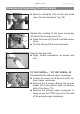
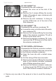
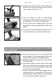
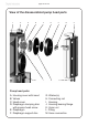
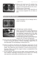
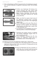
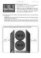
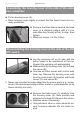
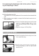
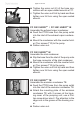
Table Of Contents
- Part I
- Reset / Language selection
- Safety information!
- Technical data
- Use and operation
- Installing a pump in a vacuum system
- Notes regarding the (dry) ice condenser
- Notes concerning the operation of the inlet condenser IK
- Notes concerning the operation of the Peltronic emission condenser
- Notes concerning the operation of pumping units with silencer
- During operation
- Important notes regarding the use of gas ballast
- Important notes concerning the operation of the exhaust waste vapor condenser
- Shutdown & storage
- CVC 3000 Vacuum controller
- Menu guide
- Pump down function
- Vac Control function
- Auto mode
- Program function
- VACUULAN function
- Application examples
- Configuration
- Part II
- Readjustment of CVC 3000
- Calibration in the factory
- Cleaning the pressure transducer
- Interface parameters
- Accessories
- Troubleshooting
- Replacing diaphragms and valves
- Cleaning and inspecting the pump heads
- Disassembling the housing cover at the side of the emission condenser
- Replacing the diaphragm
- Assembling the housing cover at the side of the emission condenser
- Disassembling the housing cover at the side of the ON/OFF switch
- Assembling the housing cover at the side of the ON/OFF switch
- Assembling the fittings
- Cleaning and replacing components
- Notes on return to the factory
- Warranty
- Health and safety clearance form
- EC Declaration of Conformity of the Machinery
page 106 of 120
+ If the old diaphragm is difcult to separate from the diaphragm support
disc, immerse assembly in naphtha or petroleum ether. Do not inhale
vapors!
D
E F
E
F
D
➨ Position new diaphragm (E) between dia-
phragm clamping disc with square head
screw (D) and diaphragm support disc (F).
+ Note: Position diaphragm with pale side
towards diaphragm clamping disc (facing
pump chamber).
+ Make sure that the square head screw of
the diaphragm clamping disc is correctly
seated in the guide hole of the diaphragm
support disc.
➨ Lift the diaphragm at the side. Place the di-
aphragm carefully together with diaphragm
clamping disc and diaphragm support disc
in the diaphragm key.
+ Avoid damage of the diaphragm: Do not ex-
cessively bend or crease the diaphragm.
+ Assemble the original number of washers
(G) between diaphragm support disc (F)
and connecting rod (H).
➨ Screw diaphragm clamping disc (D), dia-
phragm (E), diaphragm support disc (F),
and washers (G) to connecting rod (H).
➨ Optimum torque for the diaphragm support disc: 3 ft
.
lb
f
(4 Nm).
+ If necessary, put the pumping unit in its upright position to screw the
diaphragm clamping disc to the connecting rod. Subsequently lay the
pumping unit again on its side.
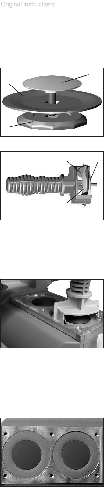
➨ Bring the diaphragms (E) into a position, in
which they are in contact with the housing
(I) and centered with respect to the bore.