
emission condenser Peltronic Manual
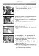
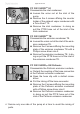
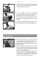
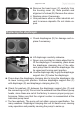
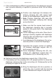
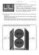
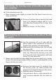
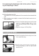
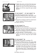
Table Of Contents
- Part I
- Reset / Language selection
- Safety information!
- Technical data
- Use and operation
- Installing a pump in a vacuum system
- Notes regarding the (dry) ice condenser
- Notes concerning the operation of the inlet condenser IK
- Notes concerning the operation of the Peltronic emission condenser
- Notes concerning the operation of pumping units with silencer
- During operation
- Important notes regarding the use of gas ballast
- Important notes concerning the operation of the exhaust waste vapor condenser
- Shutdown & storage
- CVC 3000 Vacuum controller
- Menu guide
- Pump down function
- Vac Control function
- Auto mode
- Program function
- VACUULAN function
- Application examples
- Configuration
- Part II
- Readjustment of CVC 3000
- Calibration in the factory
- Cleaning the pressure transducer
- Interface parameters
- Accessories
- Troubleshooting
- Replacing diaphragms and valves
- Cleaning and inspecting the pump heads
- Disassembling the housing cover at the side of the emission condenser
- Replacing the diaphragm
- Assembling the housing cover at the side of the emission condenser
- Disassembling the housing cover at the side of the ON/OFF switch
- Assembling the housing cover at the side of the ON/OFF switch
- Assembling the fittings
- Cleaning and replacing components
- Notes on return to the factory
- Warranty
- Health and safety clearance form
- EC Declaration of Conformity of the Machinery
page 108 of 120
Assembling the housing cover at the side of the emis-
sion condenser
➨ Put on housing cover (A).
+ Move housing cover slightly to ensure that the head covers are cor-
rectly positioned.
➨ Screw in the Allen head screws at the head
cover in a diagonal pattern with a 4 mm
wide Allen key, loosely at rst, to align, then
tighten.
+ Maximum torque: 4.4 ft
.
lb
f
(6 Nm).
Disassembling the housing cover at the side of the ON/
OFF switch
➨ Lay the pumping unit on its side with the
pump heads to be maintained at the top.
Support the pumping unit appropriately.
➨ Disassemble the housing cover (A) to check
the valves (B).
➨ Unscrew six Allen screws with a 4mm wide
Allen key. Remove the housing cover with
housing cover insert (A) together with head
covers (C) and valves (B).
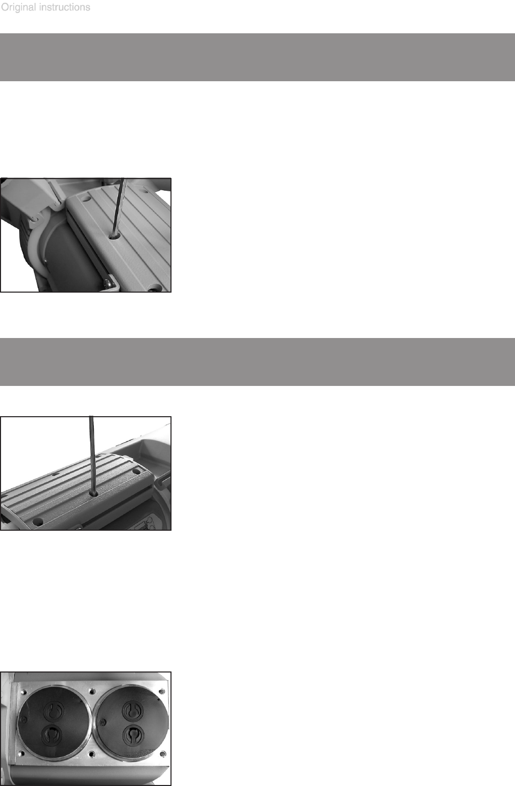
+ Never use a pointed or sharp-edged tool to remove parts (e.g., screw-
driver). We recommend using a rubber mallet or compressed air (to be
blown carefully into port).
➨ Remove the head cover (C) carefully from
the housing cover (A). Note position and
alignment of valves (B). Remove the valves.
+ Replace valves if necessary.
+ Use petroleum ether or other industrial sol-
vent to remove deposits. Do not inhale va-
pors.