
emission condenser Peltronic Manual
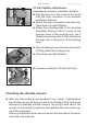
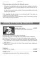

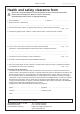
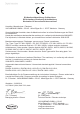
Table Of Contents
- Part I
- Reset / Language selection
- Safety information!
- Technical data
- Use and operation
- Installing a pump in a vacuum system
- Notes regarding the (dry) ice condenser
- Notes concerning the operation of the inlet condenser IK
- Notes concerning the operation of the Peltronic emission condenser
- Notes concerning the operation of pumping units with silencer
- During operation
- Important notes regarding the use of gas ballast
- Important notes concerning the operation of the exhaust waste vapor condenser
- Shutdown & storage
- CVC 3000 Vacuum controller
- Menu guide
- Pump down function
- Vac Control function
- Auto mode
- Program function
- VACUULAN function
- Application examples
- Configuration
- Part II
- Readjustment of CVC 3000
- Calibration in the factory
- Cleaning the pressure transducer
- Interface parameters
- Accessories
- Troubleshooting
- Replacing diaphragms and valves
- Cleaning and inspecting the pump heads
- Disassembling the housing cover at the side of the emission condenser
- Replacing the diaphragm
- Assembling the housing cover at the side of the emission condenser
- Disassembling the housing cover at the side of the ON/OFF switch
- Assembling the housing cover at the side of the ON/OFF switch
- Assembling the fittings
- Cleaning and replacing components
- Notes on return to the factory
- Warranty
- Health and safety clearance form
- EC Declaration of Conformity of the Machinery

page 111 of 120
PC 3001 VARIO
pro
EK Peltronic
Assemble the emission condenser Peltronic.
➨ Slip the hose from the outlet of the pump
onto the hose connector of the emission
condenser Peltronic.
➨ Attach the hose connection with hose clip.
Close hose clip with at pliers.
➨ Attach the mounting plate of the emission
condenser Peltronic with 2 screws at the
housing cover of the pumping unit; use a
Phillips screw driver size 2. Pay attention to
the cage nuts in the groove of the housing
cover.
➨ Slip connecting hose onto hose connection
of tting below the housing cover.
➨ Close hose clip with at pliers.
➨ Assemble catchpots (10) with joint clips.
Checking the ultimate vacuum
➨ After any intervention at the equipment (e.g., repair / maintenance)
the ultimate vacuum of the pump has to be checked. Only if the pump
achieves its specied ultimate vacuum, the pump’s leak rate is low
enough to ensure that no explosive atmospheres will occur in the inte-
rior of the equipment.
After any intervention at the vacuum sensor the leak rate of the equip-
ment has to be checked.