
emission condenser Peltronic Manual

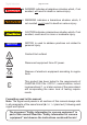

Table Of Contents
- Part I
- Reset / Language selection
- Safety information!
- Technical data
- Use and operation
- Installing a pump in a vacuum system
- Notes regarding the (dry) ice condenser
- Notes concerning the operation of the inlet condenser IK
- Notes concerning the operation of the Peltronic emission condenser
- Notes concerning the operation of pumping units with silencer
- During operation
- Important notes regarding the use of gas ballast
- Important notes concerning the operation of the exhaust waste vapor condenser
- Shutdown & storage
- CVC 3000 Vacuum controller
- Menu guide
- Pump down function
- Vac Control function
- Auto mode
- Program function
- VACUULAN function
- Application examples
- Configuration
- Part II
- Readjustment of CVC 3000
- Calibration in the factory
- Cleaning the pressure transducer
- Interface parameters
- Accessories
- Troubleshooting
- Replacing diaphragms and valves
- Cleaning and inspecting the pump heads
- Disassembling the housing cover at the side of the emission condenser
- Replacing the diaphragm
- Assembling the housing cover at the side of the emission condenser
- Disassembling the housing cover at the side of the ON/OFF switch
- Assembling the housing cover at the side of the ON/OFF switch
- Assembling the fittings
- Cleaning and replacing components
- Notes on return to the factory
- Warranty
- Health and safety clearance form
- EC Declaration of Conformity of the Machinery
page 15 of 120
The supply cable may be tted with a molded Europe-
an IEC plug or a plug suitable for your local electrical
supply. The cable contains wires color coded as fol-
lows: green or green and yellow: ground; blue or white:
neutral; brown or black: hot.
+ Due to the high compression ratio, the pump may gen-
erate overpressure at the outlet. Check pressure com-
patibility with system components (e.g., exhaust pipe-
line or exhaust valve) at the outlet.
+ Do not permit any uncontrolled pressurizing. Make
sure that the exhaust pipeline cannot become blocked.
If there is an exhaust isolation valve, make sure that you
cannot operate the equipment with the valve closed to
avoid a risk of bursting!
+ Maximum permissible pressure at the pressure trans-
ducer: 21.8 psi (1.5 bar) absolute.
+ Keep the electrical power cord away from heated sur-
faces.
• Provide a rm, level platform for the equipment. Check
that the system which you are going to evacuate is
mechanically stable. Check that all ttings are secure.
Ensure a stable position of the pump without any me-
chanical contact other than the pump feet.
• Comply with maximum permissible pressures at in-
let and outlet and with maximum permissible pres-
sure differences between inlet and outlet. See section
„Technical data“, pg. 27. Do not operate the pump
with overpressure at the inlet.
• Avoid overpressure of more than 17.5 psi absolute (1.2
bar absolute) in the event that inert gas is connected to
the pump, to the gas ballast or to a venting valve.
• Note: Flexible elements will shrink when evacuated.
• Connect hoses gas tight at inlet and outlet of the pump.