
emission condenser Peltronic Manual
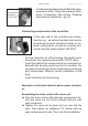
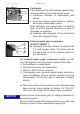

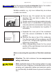


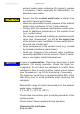
Table Of Contents
- Part I
- Reset / Language selection
- Safety information!
- Technical data
- Use and operation
- Installing a pump in a vacuum system
- Notes regarding the (dry) ice condenser
- Notes concerning the operation of the inlet condenser IK
- Notes concerning the operation of the Peltronic emission condenser
- Notes concerning the operation of pumping units with silencer
- During operation
- Important notes regarding the use of gas ballast
- Important notes concerning the operation of the exhaust waste vapor condenser
- Shutdown & storage
- CVC 3000 Vacuum controller
- Menu guide
- Pump down function
- Vac Control function
- Auto mode
- Program function
- VACUULAN function
- Application examples
- Configuration
- Part II
- Readjustment of CVC 3000
- Calibration in the factory
- Cleaning the pressure transducer
- Interface parameters
- Accessories
- Troubleshooting
- Replacing diaphragms and valves
- Cleaning and inspecting the pump heads
- Disassembling the housing cover at the side of the emission condenser
- Replacing the diaphragm
- Assembling the housing cover at the side of the emission condenser
- Disassembling the housing cover at the side of the ON/OFF switch
- Assembling the housing cover at the side of the ON/OFF switch
- Assembling the fittings
- Cleaning and replacing components
- Notes on return to the factory
- Warranty
- Health and safety clearance form
- EC Declaration of Conformity of the Machinery

page 41 of 120
- Condensate and deposits will affect the mea-
surement results. Clean the pressure trans-
ducer, if necessary. See section „Cleaning
the pressure transducer“, pg. 83.
Connecting components at the controller:
At the rear side of the controller are connec-
tions for e.g., an optional coolant valve and/or
an external pressure transducer and/or an ex-
ternal venting valve, as well as a venting con-
nection and the serial interface RS 232C.
- Pull the controller out of the housing. Be careful not to
disconnect the measuring connection (PTFE tube)!
- Insert the cable of the component to be connected un-
derneath the housing and plug into the controller. Do
not apply off-axis forces when assembling or removing
plug connections! Observe correct orientation of the
plug.
- Insert controller into the housing.
Separator at inlet and exhaust waste vapor condens-
er:
Assembling the hose nozzle with union nut:
➨ Take the hose nozzle with attached compression fer-
rule and union nut out of the catchpot and put onto
inlet connection.
➨ Tighten the union nut by hand until you can feel the
stop. Then tighten an additional 1/4 rotation with an
open-ended wrench (size 17mm) for nal installation.
measurement
connection
at CVC 3000