
emission condenser Peltronic Manual
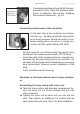
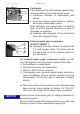

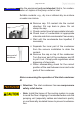


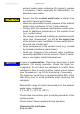
Table Of Contents
- Part I
- Reset / Language selection
- Safety information!
- Technical data
- Use and operation
- Installing a pump in a vacuum system
- Notes regarding the (dry) ice condenser
- Notes concerning the operation of the inlet condenser IK
- Notes concerning the operation of the Peltronic emission condenser
- Notes concerning the operation of pumping units with silencer
- During operation
- Important notes regarding the use of gas ballast
- Important notes concerning the operation of the exhaust waste vapor condenser
- Shutdown & storage
- CVC 3000 Vacuum controller
- Menu guide
- Pump down function
- Vac Control function
- Auto mode
- Program function
- VACUULAN function
- Application examples
- Configuration
- Part II
- Readjustment of CVC 3000
- Calibration in the factory
- Cleaning the pressure transducer
- Interface parameters
- Accessories
- Troubleshooting
- Replacing diaphragms and valves
- Cleaning and inspecting the pump heads
- Disassembling the housing cover at the side of the emission condenser
- Replacing the diaphragm
- Assembling the housing cover at the side of the emission condenser
- Disassembling the housing cover at the side of the ON/OFF switch
- Assembling the housing cover at the side of the ON/OFF switch
- Assembling the fittings
- Cleaning and replacing components
- Notes on return to the factory
- Warranty
- Health and safety clearance form
- EC Declaration of Conformity of the Machinery
page 42 of 120
Catchpots:
The catchpot at the inlet protects against drop-
lets and particles from entering the pump.
+ Enhances lifetimes of diaphragms and
valves.
+ Improves vacuum performance in applica-
tions with condensable vapors.
Both catchpots are coated with a protective
layer to protect against shattering in case of
breakage or implosion.
➨ Assemble the catchpots at the inlet and at
the outlet using joint clips.
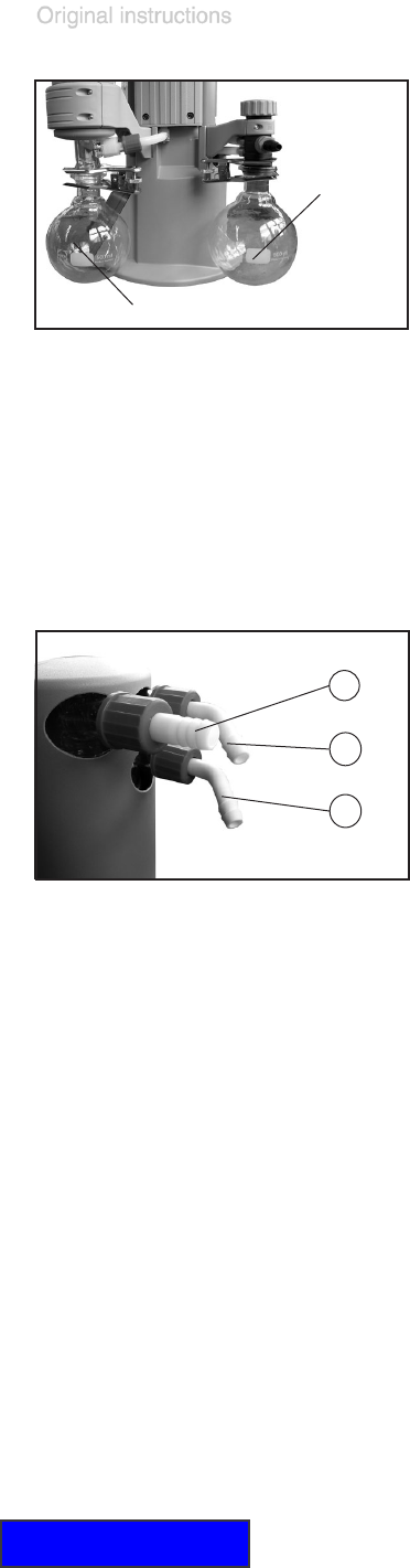
Exhaust waste vapor condenser
(PC3001 VARIO
pro
):
➨ Assemble the hose nozzles for coolant inlet
(11) and coolant outlet (12) tubing and for
the gas outlet (6) at the exhaust waste va-
por condenser.
The exhaust waste vapor condenser enables an ef-
cient condensation of the pumped vapors at the outlet.
+ No backow of condensates.
+ Controlled recovery of condensates.
+ Close to 100% solvent recovery.
+ The isolation cover protects against glass splinters in
case of breakage, acts as thermal insulation to avoid
condensation of humidity and is intended to absorb
shocks.
➨ Attach the tubing of the coolant circuit to the respective
hose nozzles (hose nozzles for tubing I.D. 1/4”-5/16”
(6-8 mm), see image) at the waste vapor condenser.
Check all hose connections prior to starting operation of
the cooling system.
Secure coolant hoses at the hose nozzles (e.g., with hose
clamps) to prevent their accidentally slipping off.
catchpot at
the inlet (10)
catchpot at the outlet (10)
11
12
6
NOTICE