
emission condenser Peltronic Manual
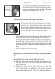
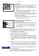

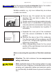


Table Of Contents
- Part I
- Reset / Language selection
- Safety information!
- Technical data
- Use and operation
- Installing a pump in a vacuum system
- Notes regarding the (dry) ice condenser
- Notes concerning the operation of the inlet condenser IK
- Notes concerning the operation of the Peltronic emission condenser
- Notes concerning the operation of pumping units with silencer
- During operation
- Important notes regarding the use of gas ballast
- Important notes concerning the operation of the exhaust waste vapor condenser
- Shutdown & storage
- CVC 3000 Vacuum controller
- Menu guide
- Pump down function
- Vac Control function
- Auto mode
- Program function
- VACUULAN function
- Application examples
- Configuration
- Part II
- Readjustment of CVC 3000
- Calibration in the factory
- Cleaning the pressure transducer
- Interface parameters
- Accessories
- Troubleshooting
- Replacing diaphragms and valves
- Cleaning and inspecting the pump heads
- Disassembling the housing cover at the side of the emission condenser
- Replacing the diaphragm
- Assembling the housing cover at the side of the emission condenser
- Disassembling the housing cover at the side of the ON/OFF switch
- Assembling the housing cover at the side of the ON/OFF switch
- Assembling the fittings
- Cleaning and replacing components
- Notes on return to the factory
- Warranty
- Health and safety clearance form
- EC Declaration of Conformity of the Machinery
page 43 of 120
➨ Prevent the discharge of dangerous gases and vapors
to the surrounding atmosphere. If appropriate, connect
the exhaust line to a suitable treatment system.
+ Never block the gas outlet ((8) hose nozzle for tubing
I.D. 3/8” (10 mm)). The exhaust hose has always to be
unobstructed and without back pressure to enable an
unhindered discharge of gases and protect the pump
valves from damage.
• Note: Install the hoses of the cooling system in a way
to avoid the ow / dripping of condensed water onto the
pumping unit (especially cables and electronic parts,
see also IP degree of protection, „Technical data“, pg.
27.
• Ensure that the coolant outlet tubing is always unob-
structed and that it cannot get blocked.
• Maximum permissible coolant pressure at the exhaust
waste vapor condenser: 87 psi (6 bar) absolute. Outlet
ow must always be unhindered.
• Comply with the maximum permissible coolant pres-
sures of additional components in the coolant circuit
(e.g., coolant valve).
• Avoid overpressure in the coolant circuit (e.g., caused
by blocked or squeezed coolant hoses).
• Only install the optional coolant valve in the supply line
of the exhaust waste vapor condenser.
Notes regarding the (dry) ice condenser
(PC 3001 TE VARIO
pro
)
The exhaust waste vapor condenser en-
ables an efcient condensation of the pumped
vapors at the outlet.
+ Close to 100% solvent recovery.
+ The isolation cover protects against glass
splinters in case of breaking, acts as ther-
mal insulation to avoid the condensation of
humidity and is intended to absorb shocks.
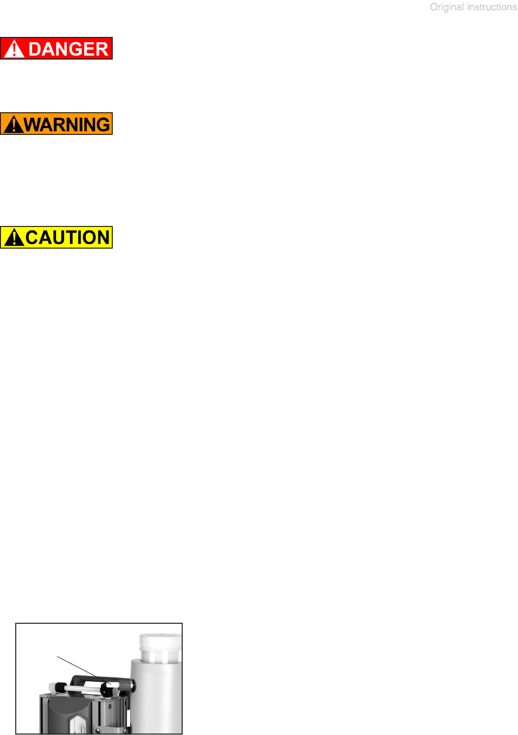
outlet (gas!)
hose nozzle