
emission condenser Peltronic Manual
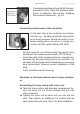
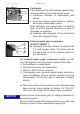

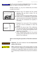


Table Of Contents
- Part I
- Reset / Language selection
- Safety information!
- Technical data
- Use and operation
- Installing a pump in a vacuum system
- Notes regarding the (dry) ice condenser
- Notes concerning the operation of the inlet condenser IK
- Notes concerning the operation of the Peltronic emission condenser
- Notes concerning the operation of pumping units with silencer
- During operation
- Important notes regarding the use of gas ballast
- Important notes concerning the operation of the exhaust waste vapor condenser
- Shutdown & storage
- CVC 3000 Vacuum controller
- Menu guide
- Pump down function
- Vac Control function
- Auto mode
- Program function
- VACUULAN function
- Application examples
- Configuration
- Part II
- Readjustment of CVC 3000
- Calibration in the factory
- Cleaning the pressure transducer
- Interface parameters
- Accessories
- Troubleshooting
- Replacing diaphragms and valves
- Cleaning and inspecting the pump heads
- Disassembling the housing cover at the side of the emission condenser
- Replacing the diaphragm
- Assembling the housing cover at the side of the emission condenser
- Disassembling the housing cover at the side of the ON/OFF switch
- Assembling the housing cover at the side of the ON/OFF switch
- Assembling the fittings
- Cleaning and replacing components
- Notes on return to the factory
- Warranty
- Health and safety clearance form
- EC Declaration of Conformity of the Machinery
page 50 of 120
exhaust waste vapor condenser (9) regularly; replace
if necessary. Check especially for deterioration, co-
alescence and cracks.
• Ensure that the coolant outlet hose is always free
and that it cannot get blocked.
• Maximum permissible coolant pressure at the exhaust
waste vapor condenser: 87 psi (6 bar) absolute
• Comply with the maximum permissible coolant pres-
sures of additional components in the coolant circuit
(e.g., coolant valve).
• We strongly recommend installing an optional coolant
valve (see „Accessories“, pg. 94) in the supply line
of the exhaust vapor condenser to save water and re-
duce the risk of water spill.
• Avoid overpressure in the coolant circuit (e.g., caused
by blocked or kinked coolant hoses).
• Avoid any clogging of the exhaust vapor condenser
caused by deposits or frozen solvents. Clean if neces-
sary or use higher coolant temperatures.
In case of condensation: Check the liquid level in both
catchpots (10) during operation. Check the liquid lev-
el regularly. Do not allow the catchpots to overll. Drain
catchpots in time to avoid overow. Install a level sensor
(see „Accessories“, pg. 94) for monitoring, if necessary.
The maximum liquid level is at approximately 80% of the
total lling level to avoid problems when removing the
catchpots.
Permissible range of coolant temperature at the exhaust
waste vapor condenser:
5 °F to 68 °F (-15°C to +20°C)
Check hose connections prior to starting operation of the
cooling system.
Check coolant hoses regularly during operation.
Removing the catchpots:
Stop process.
NOTICE