
emission condenser Peltronic Manual


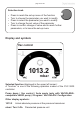

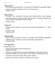
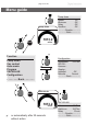

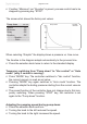
Table Of Contents
- Part I
- Reset / Language selection
- Safety information!
- Technical data
- Use and operation
- Installing a pump in a vacuum system
- Notes regarding the (dry) ice condenser
- Notes concerning the operation of the inlet condenser IK
- Notes concerning the operation of the Peltronic emission condenser
- Notes concerning the operation of pumping units with silencer
- During operation
- Important notes regarding the use of gas ballast
- Important notes concerning the operation of the exhaust waste vapor condenser
- Shutdown & storage
- CVC 3000 Vacuum controller
- Menu guide
- Pump down function
- Vac Control function
- Auto mode
- Program function
- VACUULAN function
- Application examples
- Configuration
- Part II
- Readjustment of CVC 3000
- Calibration in the factory
- Cleaning the pressure transducer
- Interface parameters
- Accessories
- Troubleshooting
- Replacing diaphragms and valves
- Cleaning and inspecting the pump heads
- Disassembling the housing cover at the side of the emission condenser
- Replacing the diaphragm
- Assembling the housing cover at the side of the emission condenser
- Disassembling the housing cover at the side of the ON/OFF switch
- Assembling the housing cover at the side of the ON/OFF switch
- Assembling the fittings
- Cleaning and replacing components
- Notes on return to the factory
- Warranty
- Health and safety clearance form
- EC Declaration of Conformity of the Machinery

page 55 of 120
The CVC 3000 controller can be adapted to the specic application by
choosing the appropriate function depending on the connected compo-
nents and the requirements of the application.
Automatic detection of the components
When switching on the controller, the conguration of the connected com-
ponents is checked automatically.
Connected components (e.g., VACUU•BUS-compatible VARIO pumps,
gauge heads 3000 series, valves, level sensors) are detected automati-
cally and controlled by the CVC 3000 until the controller is switched off.
Identical components must be congured beforehand; information upon
request. Switch the controller off and on again to renew the conguration.
The last mode of operation and the preselected values (e.g., for pres-
sure, speed or time for automated switching off) are stored.
If the preselections are chosen appropriately, it is possible to start imme-
diately if similar operating conditions are desired.
The controller features ve functions and one conguration menu,
see section ”Menu guide”. Each of these functions involves different menu
options, which are presented automatically and reect the connected
components. The types of components connected (e.g., valves) de-
termine the active menu items.
Changing the function:
➨ Switch controller on.
➨ Press ”START/STOP” key to terminate control in case control is run-
ning (e.g., if ”Autostart” is activated).
➨ Press ”MODE” key.
➨ Select function with knob and press to conrm.
+ Depending on the selected function and system components, the con-
troller provides different operating control, as follows:
’’Pump down’’
• Manages the continuous speed control of the VACUU•BUS-compatible
VARIO pump depending on preselected pressure and time settings.
• Coolant valve
Notes on selecting the function