
emission condenser Peltronic Manual


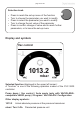

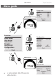

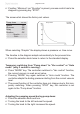
Table Of Contents
- Part I
- Reset / Language selection
- Safety information!
- Technical data
- Use and operation
- Installing a pump in a vacuum system
- Notes regarding the (dry) ice condenser
- Notes concerning the operation of the inlet condenser IK
- Notes concerning the operation of the Peltronic emission condenser
- Notes concerning the operation of pumping units with silencer
- During operation
- Important notes regarding the use of gas ballast
- Important notes concerning the operation of the exhaust waste vapor condenser
- Shutdown & storage
- CVC 3000 Vacuum controller
- Menu guide
- Pump down function
- Vac Control function
- Auto mode
- Program function
- VACUULAN function
- Application examples
- Configuration
- Part II
- Readjustment of CVC 3000
- Calibration in the factory
- Cleaning the pressure transducer
- Interface parameters
- Accessories
- Troubleshooting
- Replacing diaphragms and valves
- Cleaning and inspecting the pump heads
- Disassembling the housing cover at the side of the emission condenser
- Replacing the diaphragm
- Assembling the housing cover at the side of the emission condenser
- Disassembling the housing cover at the side of the ON/OFF switch
- Assembling the housing cover at the side of the ON/OFF switch
- Assembling the fittings
- Cleaning and replacing components
- Notes on return to the factory
- Warranty
- Health and safety clearance form
- EC Declaration of Conformity of the Machinery

page 60 of 120
The screen-shot shows the factory-set values.
When selecting ”Graphic” the display shows a pressure vs. time curve.
The timeline in the diagram adapts automatically to the process time.
+ Press the selection knob twice to return to the standard display.
Temporary switching from ”Pump down” to ”Vac control” or ”Auto
mode” (only if control is running):
+ Press ”MODE” key. The controller switches to ”Vac control” function,
the current vacuum is used as set value.
+ Pressing ”MODE” key again switches to ”Auto mode” function. The
controller adapts the boiling pressure starting from the current vacuum
level.
+ The preset function of the controller does not change due to this tem-
porary switching. When pressing ”STOP” key, the controller is set
again to the ”Pump down” function.
Adapting the pumping speed during pump down:
+ Press the selection knob and turn.
+ Turning the knob to the left reduces the speed.
+ Turning the knob to the right increases the speed.
+ If neither ”Minimum” nor ”Duration” is preset, process control has to be
stopped by pressing key ”STOP”.
10 mbar
00:03:50
Pump down
Pump down
Speed HI
Minimum Off
Delay Off
Duration Off
- - - - - - Graphic - - - - - -
- - - - - - - Back - - - - - - -
760 Torr