
emission condenser Peltronic Manual


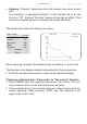

Table Of Contents
- Part I
- Reset / Language selection
- Safety information!
- Technical data
- Use and operation
- Installing a pump in a vacuum system
- Notes regarding the (dry) ice condenser
- Notes concerning the operation of the inlet condenser IK
- Notes concerning the operation of the Peltronic emission condenser
- Notes concerning the operation of pumping units with silencer
- During operation
- Important notes regarding the use of gas ballast
- Important notes concerning the operation of the exhaust waste vapor condenser
- Shutdown & storage
- CVC 3000 Vacuum controller
- Menu guide
- Pump down function
- Vac Control function
- Auto mode
- Program function
- VACUULAN function
- Application examples
- Configuration
- Part II
- Readjustment of CVC 3000
- Calibration in the factory
- Cleaning the pressure transducer
- Interface parameters
- Accessories
- Troubleshooting
- Replacing diaphragms and valves
- Cleaning and inspecting the pump heads
- Disassembling the housing cover at the side of the emission condenser
- Replacing the diaphragm
- Assembling the housing cover at the side of the emission condenser
- Disassembling the housing cover at the side of the ON/OFF switch
- Assembling the housing cover at the side of the ON/OFF switch
- Assembling the fittings
- Cleaning and replacing components
- Notes on return to the factory
- Warranty
- Health and safety clearance form
- EC Declaration of Conformity of the Machinery
page 68 of 120
Attention: If the controller is set to ”Defaults”: ”On”, all stored pro-
grams will be deleted.
Example
VACUU•BUS-compatible VARIO vacuum pump with speed control
(e.g., with a rotary evaporator): Degassing and automatic distilla-
tion with timing
Program step 1 should be always a denite initial state, here atmospheric
pressure (ATM). To reach this state denitely, set a tickmark at ”Vent.”
and ”Step” by pressing the selection knob.
In step 2, pumping begins, attempting to reach 300 Torr/mbar as quickly
as possible (”Step”). Vacuum holds there for 10 minutes (degassing the
solvent).
In step 3, ”Auto
➜
” causes an automatic search of a boiling point in
the pressure interval between 300 Torr/mbar/hPa (depending on preset
pressure unit) and 2 Torr/mbar/hPa, followed by automatic adaptation to
changes in the boiling point. The following step starts either (1) once the
cumulative process time reaches the set limit (1 hour/60 minutes), even
if the preset pressure (2 Torr/mbar/hPa) has not been reached, or (2) if
a vacuum of 2 Torr/mbar/hPa is reached, even if the preset time has not
been completed.
Step 4 vents to atmospheric pressure as fast as possible and switches off
the control after one minute.
Program
No hh:mm:ss Vac Vent. Step Auto
01 00:00:00 ATM ✔ ✔
02 00:10:00 300 ✔
03 01:00:00 2 *
04 00:01:00 ATM ✔ ✔
05 00:00:00 0
06 00:00:00 0
07 00:00:00 0
08 00:00:00 0
09 00:00:00 0
10 00:00:00 0
- - - - - - - - - - - - - Back - - - - - - - - - - - - - -
01:11:00
➜
* If the pressure difference
between the vacuum for
degassing and the expect-
ed vacuum for distillation is
very small (distillation vac-
uum >75% of the degas-
sing vacuum), select the
function ”Auto ” (adapting
the vacuum starting from
the current pressure) in-
stead of ” Auto
➜
” (at rst
searching the boiling point
automatically, and then
adapting the vacuum).
Application example