page 1 of 75 Technology for Vacuum Systems Instructions for use ME 4C NT VARIO MZ 2C NT VARIO MD 4C NT VARIO MV 10C VARIO-B MD 12C VARIO-B PC 3002 VARIO PC 3003 VARIO PC 3004 VARIO PC 3010 VARIO PC 3012 VARIO Speed controlled chemistry diaphragm pumps and chemistry pumping units Documents are only to be used and distributed completely and unchanged. It is strictly the users’ responsibility to check carefully the validity of this document with respect to his product. Manual-no.
page 2 of 75 Dear customer, Your VACUUBRAND diaphragm pumps should support you for a long time without trouble and with maximal power. Thanks to our long practical experience we have much information how you could ensure powerful application and personal safety. Please read these instructions for use before the initial operation of your pump.
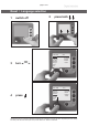
page 3 of 75 Reset / Language selection 1 switch off 2 press both C V C 3000 3 turn D eutsch E nglish Français Italiano E spañol Türkçe P ortuguê Ρ yccкий P olski N ederl. 日本語 한국어 中文 C V C 3000 4 press V 2.0 D eutsch E nglish Français Italiano E spañol Türkçe V 2.0 Portuguê Ρyccкий Polski N ederl. 日本語 한국어 中文 Documents are only to be used and distributed completely and unchanged.
page 4 of 75 Contents Reset / Language selection......................................................................................3 Safety information!......................................................................................................5 General information.............................................................................................................................5 Intended use............................................................................................
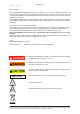
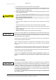
page 5 of 75 Safety information! General information NOTICE ☞ Read and comply with this manual before installing or operating the equipment. ☞ Transport the pump at the provided handles or recessed grips. Remove all packing material, remove the product from its packing-box, remove the protective covers from the inlet and outlet ports and keep. Inspect the equipment.
page 6 of 75 ☞ Provide always a free and pressureless exhaust pipeline. + Ensure that the system design does not allow the coolant outlet pipeline to become blocked. Install an optional coolant valve always in the supply line of the exhaust waste vapour condenser only. + Check the overpressure safety relief device at the exhaust waste vapour condenser in appropriate intervals.
page 7 of 75 Operating conditions ➨ The pumps have no approval for operation in or for pumping of potentially explosive atmospheres. ➨ The pumps are not suitable to pump - unstable substances, - substances which react explosively under impact (mechanical stress) and/or when being exposed to elevated temperatures without air. - self inflammable substances, - substances which are inflammable without air and - explosive substances.
page 8 of 75 ☞ Attention: In case of pressures above approximately 1080 mbar the pressure reading gets incorrect (saturation of the pressure transducer). The display flashes. Immediate pressure relief necessary! Risk of bursting! • Comply with applicable regulations when disposing of chemicals. Take into consideration that chemicals may be polluted.
page 9 of 75 The A-weighted emission sound pressure level of the pump does not exceed 70 dB(A). Measurement according to EN ISO 2151:2004 and EN ISO 3744:1995 with standard silencer or exhaust tube at outlet. Maintenance and repair NOTICE Wear parts have to be replaced regularly. In case of normal wear the lifetime of the diaphragms and valves is > 10000 operating hours. Bearings have a typical durability of 40000 h.
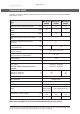
page 10 of 75 Technical data The pump achieves its ultimate pumping speed and ultimate vacuum only at operating temperature (after approx. 15 min.). Type ME 4C NT VARIO MZ 2C NT VARIO MD 4C NT VARIO Maximum pumping speed (ISO 21360) m3/h 4.9 2.8 4.6 Ultimate vacuum (absolute) without gas ballast* mbar 70 7 1.
page 11 of 75 Type PC 3002 VARIO PC 3003 VARIO PC 3004 VARIO Maximum pumping speed (ISO 21360)* m3/h 2.8 2.8 4.6 Ultimate vacuum (absolute) without gas ballast** mbar 7 0.6 1.5 Ultimate vacuum (absolute) with gas ballast** mbar 12 2 3 Maximum permissible inlet pressure (absolute) bar Maximum permissible outlet pressure (absolute) Maximum permissible pressure (absolute) at gas ballast valve 1.1 bar 1.1 bar 1.
page 12 of 75 MV 10C VARIO-B MD 12C VARIO-B PC 3010 VARIO PC 3012 VARIO Type Maximum pumping speed (ISO 21360)* m3/h 8.6 10.0 Ultimate vacuum (absolute) without gas ballast** mbar 0.6 2 Ultimate vacuum (absolute) with gas ballast** mbar 9 9 Maximum permissible inlet pressure (absolute) bar Maximum permissible outlet pressure (absolute) 1.1 bar Maximum permissible pressure (absolute) at gas ballast valve 1.1 bar 1.
page 13 of 75 Controller CVC 3000 ceramic diaphragm (alumina), capacitive, absolute pressure, gas type independent Pressure transducer Display LCD graphic display, illuminated Pressure units / scale (selectable) mbar, Torr or hPa Measuring range (absolute) 1080 mbar - 0.1 mbar (810 Torr - 0.1 Torr) Maximum control range with internal pressure transducer (absolute)* 1060 mbar - 1 mbar (795 Torr - 1 Torr) Turbo mode < 1 mbar (Torr) Resolution 0.
page 14 of 75 Wetted parts Components Wetted materials Pump Head cover ETFE carbon fibre reinforced Diaphragm clamping disc ETFE carbon fibre reinforced Diaphragm PTFE Valves FFKM (ME 4C NT VARIO: PTFE) O-rings FPM Valve head (pumps NT VARIO) ECTFE carbon fibre reinforced Housing cover insert (pumps VARIO-B / PC 301x) PTFE carbon reinforced Gas ballast tube, inlet, outlet (pumps NT VARIO) PTFE carbon reinforced Inlet (pumps VARIO-B) Stainless steel Outlet (pumps VARIO-B) ETFE Silencer /
page 15 of 75 Pump parts Position Component Position Component 1 Diaphragm pump NT VARIO 11 Recessed grip / handle 2 Controller CVC 3000 12 VACUU•BUS cable to controller 3 Mains connection 13 Exhaust waste vapour condenser 4 ON/OFF switch 14 Catchpot 5 Pump rating plate 15 Coolant inlet 6 Fan 16 Coolant outlet 7 Inlet 17 Overpressure safety relief device 8 Outlet 18 Catchpot (inlet) 9 Gas ballast valve 19 Drain screw 10 Fuse holder 20 Collecting flask (outlet)
page 16 of 75 MZ 2C NT VARIO 4 3 1 11 11 12 7 6 9 6 8 10 2 5 4 MD 4C NT VARIO 7 9 3 1 11 12 11 8 6 10 2 5 Documents are only to be used and distributed completely and unchanged. It is strictly the users’ responsibility to check carefully the validity of this document with respect to his product. Manual-no.
page 17 of 75 PC 3002 VARIO 11 5 9 16 15 8 2 1 13 11 7 17 underside terminal box: 10 14 PC 3003 VARIO / PC 3004 VARIO 3 6 16 4 5 15 8 2 9 1 13 11 7 17 14 Documents are only to be used and distributed completely and unchanged. It is strictly the users’ responsibility to check carefully the validity of this document with respect to his product. Manual-no.
page 18 of 75 MV 10C VARIO-B / MD 12C VARIO-B outlet side MV 10C VARIO-B 10 11 4 3 12 9 5 8 7 6 2 8 outlet side MD 12C VARIO-B PC 3010 VARIO / PC 3012 VARIO 16 8 7 4 3 5 2 11 18 1 19 17 13 15 20 Documents are only to be used and distributed completely and unchanged. It is strictly the users’ responsibility to check carefully the validity of this document with respect to his product. Manual-no.
page 19 of 75 Rear side CVC 3000 bushes for connection of VACUU•BUS components (e.g. coolant valve) measurement connection Connection of the VACUU • BUS line to NT VARIO / VARIO-B pump venting connection serial interface RS 232 C stand foot, removable, also for mounting in a rod clamp (pumps only) Documents are only to be used and distributed completely and unchanged. It is strictly the users’ responsibility to check carefully the validity of this document with respect to his product. Manual-no.
page 20 of 75 Use and operation When switching on the controller CVC 3000 for the very first time, a menu to select the language of the controller menu is displayed. Select the desired language (e.g. ”English”) by turning the selection knob and press to confirm. Then select the pressure unit (”mbar”, ”Torr” or ”hPa”) in the same way. It is possible to access the language selection menu at any time by switching on the controller while keeping the selection knob pressed.
page 21 of 75 CVC 3000 The CVC 3000 is equipped with an internal capacitive pressure transducer with ceramic diaphragm to measure the actual pressure independently of the gas type and with reference to the vacuum, i. e. absolute. Pumps NT VARIO and VARIO-B: + Connect the controller CVC 3000 via the VACUU•BUS cable of the NT VARIO or VARIO-B pump to the diaphragm pump. Attention: Do not cant when assembling or removing plug connections! Obey correct positioning of the plug.
page 22 of 75 Exhaust waste vapour condenser: ➨ Assemble hose nozzles for coolant inlet and coolant outlet pipelines at the exhaust waste vapour condenser. PC 301x VARIO 8 The exhaust waste vapour condenser enables an efficient condensation of the pumped vapours at the outlet. + No backflow of condensates. + Controlled recovery of condensates. + Next to 100% solvent recovery.
page 23 of 75 If pumping condensable vapours (water vapour, solvents, ....), let the pump run with gas ballast to reduce condensation in the pump. Operation with silencer at the outlet: Operating the pump at high inlet pressure or pumping dusty gases for a long time may cause clogging of the silencer. Check the silencer regularly and replace if necessary. In case of excess temperature, the motor is shut down by a thermal cutout in the winding. Attention: Reset possible only manually.
page 24 of 75 Attention: Notes concerning the operation of the exhaust waste vapour condenser + The gas outlet (hose nozzle 10 mm) must not be blocked. The exhaust pipeline has always to be free and pressureless to enable an unhindered discharge of gases. + Connect the exhaust to a suitable treatment plant to prevent the discharge of dangerous gases and vapours to the surrounding atmosphere. + Ensure that the coolant outlet pipeline is always free and that it cannot get blocked.
page 25 of 75 Shutdown NOTICE Short-term: Has the pump been exposed to condensate? - Allow the pump to continue to run at atmospheric pressure for a few minutes (continuous pumping). Has the pump been exposed to media which may damage the pump materials or forms deposits? - Check and clean pump heads if necessary. Long-term: - Take measures as described in section short-term shutdown. - Separate pump from the application. Close gas ballast valve. - Drain catchpots. - Close inlet and outlet port (e.
page 26 of 75 Vacuum Controller CVC 3000 When switching on the controller CVC 3000 for the very first time, a menu to select the language of the controller menu is displayed. Select the desired language e.g., ”English” by turning the selection knob and press to confirm. Then select the pressure unit (”mbar”, ”Torr” or” hPa”) in the same way. It is possible to access the language selection menu at any time by switching on the controller while keeping the selection knob pressed.
page 27 of 75 Display and symbols Function of the device: (displayed in the upper left corner) Vac control Pump down Vac control Auto mode (only with NT VARIO pump) Program VACUULAN Configuration 100 1013.2 mbar 100 100 1013.
page 28 of 75 Notes on selecting the function The controller CVC 3000 can be adapted to the specific application by choosing the appropriate function depending on the connected components and the requirements of the application. Automatic detection of the components When switching on the controller the actual configuration of the connected components is checked automatically.
page 29 of 75 Menu guide Vac control Pump down Speed HI Minimum Off Delay Off Duration Off - - - - - - Graphic - - - - - - - - - - - - Back - - - - - - Pump down Vac control 1013.2 1013.
page 30 of 75 Function Pump down ➨ Continuous pumping with pressure and time settings • Operation on demand of a speed controlled NT VARIO / VARIO-B pump Preselections ☞ Use the selection knob to select the parameters. All parameters can be altered even while operation control is running. ☞ Speed: Preselection of the motor speed for pump down. The selection ”HI” effects the maximum speed and best ultimate vacuum of the pump (with automatic speed reduction at ultimate vacuum).
page 31 of 75 Temporary switching from ”Pump down” to ”Vac control” or ”Auto mode” (only if control is running): ☞ Press key ”MODE”. The controller switches to function ”Vac control”, the current vacuum is used as set value. ☞ Pressing key ”MODE” again switches to function ”Auto mode”. The controller adapts the boiling pressure starting from the current vacuum. ☞ The preset function of the controller does not change due to this temporary switching.
page 32 of 75 Function Vac control ➨ Vacuum control to a preset vacuum value • Operation on demand of a speed controlled pump (NT VARIO / VARIO-B) Preselections + Use the selection knob to select the parameters. All parameters can be altered even while operation control is running. ☞ Set vacuum: The ”Set vacuum” is the set point for vacuum control with pinpoint precision for NT VARIO / VARIO-B pumps. The selection ”Turbo” leads to the optimum backing pressure for a turbomolecular pump.
page 33 of 75 Temporary switching from ”Vac control” to ”Auto mode” while process control is running: ☞ Press key MODE. The controller switches to ”Auto mode” and adapts the boiling pressure starting with the actual set value. The preset function of the controller does not change due to this switching. When pressing key ”STOP” the controller is in function ”Vac control” again. Adjustment of the set vacuum during vacuum control: Dynamic, interactive adaptation: + Press the selection knob and keep pressed.
page 34 of 75 Function Auto mode ➨ Control of a NT VARIO / VARIO-B pump in function auto mode: Automatic determination of the boiling vacuum and automatic adaptation of the boiling vacuum in case of changing process parameters. Preselections ☞ Use the selection knob to set the parameters. ☞ Sensitivity: The ”Sensitivity” of the control effects the control speed. High sensitivity leads to a reduced pumping down speed, e. g. for small amounts of solvents or foaming processes.
page 35 of 75 Function Program ➨ Ten programs with up to ten program steps with preset values for vacuum and time can be set and stored. ➜ ☞ Edit: Preset values for the process run can be edited: Time: Process runtime for each program step to reach a preset vacuum level or if setting ”Step” runtime after having achieved the vacuum level. The summed up total process runtime is shown in the base line.
page 36 of 75 The last process (not in function VACUULAN) is stored in the temporary data memory as long as the controller stays switched on. This program can be transferred to a storage space and edited. Once the program is finished, the clock symbol starts to flash. Confirm the end of the program by pressing START/STOP (clock symbol will disappear).
page 37 of 75 Function VACUULAN ➨ Optimised vacuum control for vacuum networks (e.g. VACUUBRAND VACUU•LAN) • Operation on demand of a speed controlled pump (NT VARIO / VARIO-B) Preselections ☞ Use the selection knob to select the parameters. ☞ Set vacuum (lower switch-off value): If the pressure drops below the ”Set vacuum” a time-meter starts to run; additionally the motor speed is reduced. The time-meter is reset, if the pressure exceeds the pressure value for switching on again (”Switch on”).
page 38 of 75 Examples for use Assembly of a vacuum system ☞ Assemble vacuum connection lines between vacuum pump, CVC 3000 and vacuum application. + Assemble the vacuum connection line between the controller and the vacuum application, if the controller is not part of a pumping unit. ☞ Assemble electrical connections. ☞ Connect coolant if necessary. Vacuum for filtration and suction ☞ Select function ”Pump down”. ☞ If necessary set value for ”Speed” (high or low pumping speed).
page 39 of 75 Vacuum for distillation and evaporation (e. g. rotary evaporator) Semi-automatic distillation and evaporation ☞ Select function ”Pump down”. ☞ Start process by pressing key ”START/STOP”. ☞ Observe process. As soon as evaporation starts, press key ”MODE” (switching to ”Vac control”). The vacuum level is kept constant (at the boiling pressure). Fine tuning of the vacuum value is possible by turning the selection knob.
page 40 of 75 Function Configuration In the menu ”Configuration” the device parameters are preselected. Preselections ☞ Use the selection knob to select the parameters. ☞ Adjustment: Adjustment of the pressure transducer under vacuum and/or at atmospheric pressure, see also section ”Readjustment of CVC 3000”. Adjustment at atmospheric pressure is carried out at an absolute pressure value between 1060 - 700 mbar and under vacuum at an absolute vacuum value between 0 - 20 mbar.
page 41 of 75 Readjustment of CVC 3000 NOTICE The vacuum gauge was adjusted using factory standards, which are traceable through regular calibration in an accredited laboratory (German Calibration service) to the German national pressure standard. Depending on the process and/or accuracy requirements, check the adjustment and readjust if necessary. For readjustment, the device has to be adjusted both at atmospheric pressure as well as under vacuum but only if the reference pressures are certainly known.
page 42 of 75 Calibration in the factory Control of measuring equipment The VACUUBRAND DKD calibration laboratory is accredited by the Physikalisch-Technische Bundesanstalt (PTB; German national institute for science and technology and the highest technical authority of the Federal Republic of Germany for the field of meteorology and certain sectors of safety engineering) for the measurable variable pressure in the pressure range from 10-3 mbar to 1000 mbar in accordance with the general criteria for the
page 43 of 75 Read commands ”CVC 2000” Operation Command Response current pressure IN_PV_1 XXXX mbar or XXXX Torr or XXXX hPa current frequency XX.
page 44 of 75 Write commands ”CVC 2000” Operation Command Parameter function OUT_MODE X Description 1: continuous pumping 2: vacuum control without automatic 3: vacuum control with automatic (optional) 30: sensitivity: low 31: sensitivity: normal 32: sensitivity: high set vacuum OUT_SP_1 XXXX unit according to preselection (0001 to 1060 mbar (hPa) or 0001 to 0795 Torr) set vacuum OUT_SP_V XXXX with venting* unit according to preselection (0001 to 1060 mbar (hPa) or 0001 t
page 45 of 75 Read commands ”CVC 3000” Operation Command Response Description current IN_PV_1 pressure current speed IN_PV_2 XXXX.X mbar/Torr/hPa unit according to preselections XXX% 1-100% or HI time IN_PV_3 pressure IN_PV_X operation time IN_PV_T of the controller XX:XX h:m XXXX.X XXXX.X ...
page 46 of 75 Read commands ”CVC 3000” Operation Command Status process control IN_STAT Fault status IN_ERR Response Description XXXXXX 0 control off 1 pump down/ determining boiling point 2 set vacuum reached/ boiling pressure found 3 current pressure below set vacuum/ automatic switch-off 0 VACUULAN 1 Pump down 2 Vac control 3 Auto mode 4 Program 5 measurement device 0: venting valve closed 1: venting valve open 0: coolant valve closed 1: coolant valve open 0: in-line valve clos
page 47 of 75 Read commands ”CVC 3000” Operation Command Response Description IN_SP_1 XXXX mbar or XXXX Torr or XXXX hPa set vacuum IN_SP_2 XXX% maximum speed (100% = ”HI”) IN_SP_3 XXXX mbar or XXXX Torr or XXXX hPa switching on pressure for VACUULAN or two point control IN_SP_4 XX:XX h:m delay (00:00 = Off) IN_SP_5 XXXX mbar or XXXX Torr or XXXX hPa switch off pressure (”Maximum” for ”Vac control”, ”Minimum” for ”Pump down”) IN_SP_6 XX:XX h:m process runtime time pressure IN_SP_P1y
page 48 of 75 Write commands ”CVC 3000” Operation Command Parameter Description function OUT_MODE X 0: VACUULAN 1: Pump down 2: Vac control 3: Auto mode 4: Program Attention: If control is running only switching from 1 to 2, 2 to 3 and 3 to 2 is possible with takeover of the set vacuum.
page 49 of 75 Write commands ”CVC 3000” Operation mode Command Parameter Description START X 1 started STOP X 0 Stop and delete fault 1 Stop 2 Stop with adopting the set vacuum REMOTE* X ECHO** X CVC X OUT_VENT X 0 Echo off 1 Echo on, write command with return value 2 CVC 2000 commands 3 CVC 3000 commands*** 0 venting valve closed 1 venting valve open 2 venting until atmospheric pressure store settings permanently, if Echo ”1” after realisation STORE OUT_SENSOR 0 Remote off 1 Remote on
page 50 of 75 Cleaning the pressure transducer NOTICE ➨ Attention: Never use a spiky or sharp-edged tool to clean the pressure transducer. ➨ Never touch the ceramic diaphragm of the pressure transducer with hard objects. ➨ Fill the measurement chamber with a solvent (e. g. benzene) and allow sufficient cleaning time. Observe all regulations concerning usage and disposal of solvents! ➨ Drain the solvent and dispose of in accordance with regulations, repeat cleaning if necessary.
page 51 of 75 Ways to connect pumping units PC 300x VARIO: Modification kit for small flange KF DN 16 at inlet.....................................................................699939 Hose nozzle DN 6/10 mm, for inlet...............................................................................................636635 Elbow piece (90°) for PTFE tubing DN 10/8 mm for assembly at inlet........................................637873 PTFE tubing DN 10/8 mm (sold by meter).......................................
page 52 of 75 Troubleshooting Fault Possible cause Remedy ❑ ➨ Mains not plugged in? ✔ Plug in mains plug of NT VARIO / VARIO-B pump. ➨ Controller CVC 3000 or pump NT VARIO / VARIO-B switched off? ✔ Switch on devices. ➨ VACUU • BUS cable between ✔ pump and controller not plugged in at controller? ➨ Other causes (device defective)? ✔ Contact local distributor. ➨ Too much load (e.g. valves) connected? ✔ Check current draw of the connected devices.
page 53 of 75 Fault Possible cause ❑ ➨ ✔ NT VARIO / VARIO-B pump and VMS** (Vacuum Management System) connected? ➨ Fault at the NT VARIO / VARIO-B pump? ✔ Check pump, restart controller. Warning triangle and pump symbol are flashing, six blips*. Remedy Remove VMS. Restart controller. ❑ Clock symbol is flashing. ➨ Preselected process time is over? ✔ Confirm by pressing key START/STOP. ❑ ➨ Venting valve does not respond, valve symbol is displayed.
page 54 of 75 Fault Possible cause ❑ ➨ ✔ Outgassing substances or vapour generated in the process? Check process parameters. ➨ Diaphragms or valves defective? ✔ Replace diaphragms and/or valves. ➨ Pump too hot? ✔ Allow pump to cool down. Determine and eliminate the cause of overheating. ➨ Pressure below ”Minimum” in Auto mode? ✔ Adapt switch off pressure (”Minimum”) if necessary. ➨ Loud exhaust noise? ✔ Connect hose or silencer to pump outlet.
page 55 of 75 Replacing diaphragms and valves NOTICE All bearings are encapsulated and are filled with long-life lubricant. Under normal operating conditions, the pump is maintenance free. The valves and diaphragms are wear parts. If the rated ultimate vacuum is no longer achieved or in case of increased noise level, the pump interior, the diaphragms and the valves must be cleaned and the diaphragms and valves must be checked for cracks or other damage.
page 56 of 75 Cleaning and inspecting the pump heads (pumps NT VARIO / PC 300x VARIO) Tools required (metric): - - - - - Torx screw driver TX20 Hex key size 5 Flat-bladed screw driver 2.5 mm Flat pliers Diaphragm key w/f 66 The replacement of the diaphragm and the replacement of the valves can be carried out separately. + To replace the valves, remove the head covers of one side of the pump conjointly with the assembled valve heads and fittings.
page 57 of 75 Fittings and tubing of the different pump models: ME 4C NT VARIO MZ 2C NT VARIO MD 4C NT VARIO PC 3002 VARIO Documents are only to be used and distributed completely and unchanged. It is strictly the users’ responsibility to check carefully the validity of this document with respect to his product. Manual-no.
page 58 of 75 PC 3003 VARIO PC 3004 VARIO PC 3002/3003/3004 VARIO: ➨ Remove catchpots at inlet and outlet (see ”Use and operation”). PC 3002/3003/3004 VARIO at inlet side: ➨ Open the hose clip at the inlet of the pumping unit (hose connection to controller CVC 3000) with a flat-bladed screw driver (see below). ➨ Pull the tubing off the hose connector. Documents are only to be used and distributed completely and unchanged.
page 59 of 75 Opening the hose clip: ➨ Apply screw driver as shown and turn. ➨ Detach hose from hose clip at controller support. ➨ Use a Torx screw driver TX20 to unscrew the 4 screws fixating the head cover cowling. Pay attention to the washers under the screws and remove. ➨ Pull off head cover cowling carefully. Do not cant. Detach the fixing of the connection tube to the other side of the pump at the valve head.
page 60 of 75 ➨ Check for washers between the diaphragm support disc and the connecting rod. Do not mix the washers from the different pump heads. Make sure that the original number is reassembled at the individual pump head. + If the old diaphragm is difficult to separate from the support disc, immerse assembly in naphtha or petroleum ether. Do not inhale! + Too small number of washers: The pump will not attain ultimate vacuum.
page 61 of 75 Loosen the clamping brackets on the valve heads. ➨ Unscrew at each clamping bracket the two countersunk screws with a Torx screw driver TX20. Remove the clamping brackets. ➨ Remove valve heads conjointly with disc springs, connection tube if applicable, hose nozzles and connection fasteners or move the valve heads carefully aside. Note position and orientation of the valve heads. + Note position of valves. ➨ Check valves and O-rings for damages and soiling.
page 62 of 75 ➨ Bring the diaphragms into a position in which they are in contact with the housing and centred with respect to the bore. ➨ Put on head cover with valve heads and connections. + Pay attention to the correct orientation of the head covers: Housing with cylinder pin: The cylinder pin at the pump housing has to fit into the recess at the head cover. Housing with mark: Align the recess at the head cover with the mark at the pump housing.
page 63 of 75 PC 3002/3003/3004 VARIO: ➨ Assemble catchpots with joint clips. Cleaning and inspecting the pump heads (pumps VARIO-B / PC 301x VARIO) Tools: - Phillips screw driver size 2 Open-ended wrench w/f 10/14/16/17 Hex key size 5 Diaphragm key w/f 66 Disassembling the pump from the pumping unit (PC 3010/3012 VARIO) ➨ Disconnect controller from pump (VACUU•BUS cable). ➨ Detach separator from pump inlet (open clamping ring). + Avoid the release of pollutants.
page 64 of 75 ➨ Turn the fittings with an open-ended wrench (w/f 14, at outlet w/f 16) to detach the hoses from the pump heads. + Do not remove the elbow fittings from the pump heads. Through reassembly a leak may result.
page 65 of 75 Inlet side Pumps VARIO-B / Pumping units PC 301x VARIO Outlet side MV 10C VARIO-B / PC 3010 VARIO MD 12C VARIO-B / PC 3012 VARIO ➨ To check the valves and the diaphragms use a hex key to remove four socket-head screws from the pump head and remove the upper part of the housing (housing cover with housing cover insert) together with the head cover, the valves and the O-rings. + Never remove parts by using a spiky or sharp-edged tool (e.g.
page 66 of 75 Replacing the diaphragm + Check diaphragm for damage and replace if necessary. ➨ Lift diaphragm carefully sidewise. + Never use a spiky or sharp-edged tool to lift the diaphragm. ➨ Use the diaphragm key to grip the diaphragm support disc below the diaphragm. ➨ Unscrew diaphragm support disc with diaphragm and diaphragm clamping disc. ➨ Check for washers between the diaphragm support disc and the connecting rod. Do not mix the washers from the different pump heads.
page 67 of 75 Assembling the pump heads ➨ Bring connecting rod into a position in which the diaphragm is in contact with the housing and centred with respect to the bore. Reassemble in reverse order. ➨ Install head cover with O-rings, valves and housing cover with housing cover insert. + Make sure that the valves are correctly seated: Valves at the outlet with round centred opening under valve, valves at the inlet with kidney-shaped opening beside valve.
page 68 of 75 Replacing the valve at the distributor (outlet side) ➨ Use open-ended wrench (w/f 17) to loosen the union nut of the hose, which runs directly to the cover plate of the distributor, at the pump head. ➨ Use open-ended wrench (w/f 14) to turn elbow fitting 1/4 of a turn, remove hose. Do not remove the elbow fitting from the pump head. ➨ Unscrew the two countersunk head screws at the manifold cover with an Phillips screw driver and remove cover plate and manifold cover.
page 69 of 75 Reassembling the pump at the pumping units PC 3010/3012 VARIO: ➨ Lay the pump on its side: the rating plate of the pump has to be on top (support pump suitably). + Note that to install the console, the exhaust waste vapour condenser and the condensate flask must be on top. ➨ Push the console over the threads at the pump feet. ➨ Install the serrated washers. Install the hex nuts and tighten using open-ended wrench (w/f 10). Place pumping unit in normal operating position.
page 70 of 75 Replacing the device fuse fuse holder Pumps NT VARIO / PC 300x VARIO Pumps VARIO-B / PC 301x VARIO ➨ Unscrew the fuse holder using a screw driver. ➨ Replace the defective fuse by a fuse of the same type (see ”Technical data”) and reassemble holder with fuse to the pump. Documents are only to be used and distributed completely and unchanged. It is strictly the users’ responsibility to check carefully the validity of this document with respect to his product. Manual-no.
page 71 of 75 Notes on return to the factory Repair - return - DKD calibration NOTICE Safety and health of our staff, laws and regulations regarding the handling of dangerous goods, occupational health and safety regulations and regulations regarding safe disposal of waste require that for all pumps and other products the “Health and safety clearance form“ must be send to our office duly completed and signed before any equipment is dispatched to our premises.
page 72 of 75 Health and safety clearance form Declaration concerning safety, potential hazards and safe disposal of waste, e. g. used oil. Safety and health of our staff, laws and regulations regarding the handling of dangerous goods, occupational health and safety regulations, safety at work laws and regulations regarding safe disposal of waste, e. g.
page 73 of 75 Konformitätserklärung Declaration of conformity Déclaration de conformité Pumpstand / Pumping unit / Groupe de pompage ME 4C NT VARIO (120V; 2613818), (230V; 2613819) MZ 2C NT VARIO (230V; 732400, 732401, 732402) MD 4C NT VARIO (230V; 736500, 736501, 736502) PC 3002 VARIO (230V; 733500, 733501, 733502) PC 3003 VARIO (230V; 738400, 738401, 738402) PC 3004 VARIO (230V; 737500, 737501, 737502) Hiermit erklären wir, dass das oben bezeichnete Gerät in Konzeption und Bauart sowie in der von uns in
page 74 of 75 Konformitätserklärung Declaration of conformity Déclaration de conformité Pumpstand / Pumping unit / Groupe de pompage MV 10C VARIO-B (230V; 710600, 710601) MD 12C VARIO-B (230V; 710800) PC 3010 VARIO (230V; 710700, 710701, 710702) PC 3012 VARIO (230V; 710900, 710901, 710902) Hiermit erklären wir, dass das oben bezeichnete Gerät in Konzeption und Bauart sowie in der von uns in Verkehr gebrachten Ausführung den grundlegenden Anforderungen der zutreffenden, aufgeführten EU-Richtlinien entsprich
page 75 of 75 Disclaimer: Our technical literature is only intended to inform our customer. The validity of general empirical values and results obtained under test conditions for specific applications depend on a number of factors beyond our control. It is therefore strictly the users’ responsibility to very carefully check the validity of application to their specific requirements. No claims arising from the information provided in this literature will, consequently, be entertained.