
User Manual

Documents are only to be used and distributed completely and unchanged. It is strictly the users’ responsibility to check carefully
the validity of this document with respect to his product. Manual-no.: 999164 / 19/05/2009
page 61 of 75
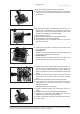
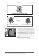
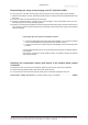
➨ Insert O-rings and valves. See gure for the correct posi-
tion of the valves:
☞ Inlet side (IN):
Marked ”IN” next to the valve seat. The valve tongue points
at the reniform orice in the valve seat.
☞ Outlet side (EX):
Marked with ”EX” next to the valve seat. The valve is ori-
ented the same way as the valve at the inlet side.
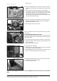
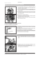
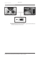
➨ Position valve heads, if applicable with hose nozzle, con-
nection tube or connection fastener, and disc springs on
the valve seats. Position disc springs with camber up-
wards. Pay attention to the correct orientation of the valve
heads.
☞ Centre the valve head with respect to the valve seat. The
valve head must lie plane within the noses of the valve
seat.
Valve head with gas ballast or hose nozzle connection:
➨ Insert square nut in the groove of the head cover or posi-
tion square nut in the groove and screw on connection
fastener afterwards.
☞ Fix llister head screw only slightly.
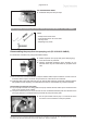
➨ Position clamping bracket with countersunk bores up-
wards.
➨ Align the countersunk bores with the threaded pegs.
➨ Fasten the countersunk screws slightly and correct the
alignment of the valve heads if necessary.
➨ Tighten countersunk screws with Torx screw driver TX20.
☞ Torque: 3 Nm.
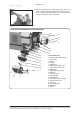
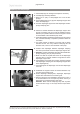
Loosen the clamping brackets on the valve heads.
➨ Unscrew at each clamping bracket the two countersunk
screws with a Torx screw driver TX20. Remove the clamp-
ing brackets.
➨ Remove valve heads conjointly with disc springs, con-
nection tube if applicable, hose nozzles and connection
fasteners or move the valve heads carefully aside. Note
position and orientation of the valve heads.
☞ Note position of valves.
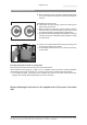
➨ Check valves and O-rings for damages and soiling.
➨ Replace valves or O-rings if necessary.
➨ Use petroleum ether or industrial solvent to remove de-
posits. Do not inhale.
EX
IN