Technology for Vacuum Systems web-based Remote Control for CVC 3000 VACUU•CONTROL® CVC 3000 for: CVC 3000 Instructions for use Original instructions EN BA-N°: 999279
Imprint Original instructions Keep for future use! This manual is only to be used and distributed in its complete and original form. It is strictly the users’ responsibility to check carefully the validity of this manual with respect to his product. Manufacturer: VACUUBRAND GMBH + CO KG Alfred‑Zippe‑Str. 4 97877 Wertheim GERMANY Phone: Head office +49 9342 808‑0 Sales +49 9342 808‑5550 Service +49 9342 808‑5660 Fax: E‑Mail: Web: +49 9342 808‑5555 info@vacuubrand.com www.vacuubrand.
Content TABLE OF CONTENT 1 Introduction 7 1.1 User information . . . . . . . . . . . . . . . . . . . . . . . . . . . . . . . 7 1.2 About this document . . . . . . . . . . . . . . . . . . . . . . . . . . . . 8 1.2.1 Symbols and icons . . . . . . . . . . . . . . . . . . . . . . . . . . . . . 8 1.2.2 Display conventions . . . . . . . . . . . . . . . . . . . . . . . . . . . . 9 1.2.3 Abbreviations . . . . . . . . . . . . . . . . . . . . . . . . . . . . . . . . 10 1.2.4 Term definition . . . . . . . . . .
Content 5 Display and operating elements 30 5.1 VACUU•CONTROL® remote control . . . . . . . . . . . . . . . 30 5.1.1 User interface . . . . . . . . . . . . . . . . . . . . . . . . . . . . . . . . 30 5.1.2 Work interface . . . . . . . . . . . . . . . . . . . . . . . . . . . . . . . 31 5.2 Operating elements . . . . . . . . . . . . . . . . . . . . . . . . . . . . . 31 5.2.1 Types of operating elements . . . . . . . . . . . . . . . . . . . . 31 5.2.2 Buttons . . . . . . . . . . . . . . . . . . . .
Content 8 Resolving problems 66 8.1 Error display . . . . . . . . . . . . . . . . . . . . . . . . . . . . . . . . . 66 8.1.1 External errors . . . . . . . . . . . . . . . . . . . . . . . . . . . . . . 66 8.1.2 Internal errors . . . . . . . . . . . . . . . . . . . . . . . . . . . . . . . . 68 8.2 Troubleshooting table . . . . . . . . . . . . . . . . . . . . . . . . . . 68 8.3 Reset to factory default settings (Reset) . . . . . . . . . . . . . 72 9 Appendix 73 9.1 Technical information . . . .
Content 6 BA-N°: 999279/17.10.
Introduction 1 Introduction This manual is part of your product. It provides important instructions for safe use of the product. Read this manual completely in order to understand proper use of your product. 1.1 User information Safety Instructions for use and safety Read this manual thoroughly and completely before using the VACUU•CONTROL® software. Keep this manual in an easily accessible location. Proper use of the CVC 3000 and VACUU•CONTROL® software is essential for safe operation.
Introduction Copyright Copyright © VACUU•CONTROL® is available as an add-on consisting of adapter with installed software and web-based graphical user interface (GUI). Unauthorized program modifications or software copies are not allowed. The content of these instructions for use is protected by copyright. Only copies for internal use are allowed, e. g., for professional training. © VACUUBRAND GMBH + CO KG Contact Contact us Please ask for replacement in case of incomplete instructions for use.
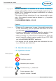
Introduction Additional icons Refers to content of this document. Refers to content of other documents. 1.2.2 Display conventions Warning levels Convention for warnings DANGER Indicates an imminent hazardous situation. Disregarding the situation will result in serious and even fatal injury or death. >> Take appropriate action to avoid dangerous situation! WARNING Indicates a potentially hazardous situation.
Introduction Design of steps Individual step (single step) >>Do the described step. 55 Result of action. Graphic Multiple steps 1. First step, 2. next step. 55 Result of action. Follow steps in the described order. 1.2.3 Abbreviations Abbreviations abs.
Introduction 1.2.4 Term definition Product specific terms VACUU•CONTROL® VACUU•CONTROL® LAN VACUU•CONTROL® WLAN VACUU•LAN® Web-based application as remote control for vacuum controller and gauges made by VACUUBRAND. Adapter LAN for connection to vacuum controller CVC 3000 or vacuum gauge DCP 3000 for integration into LAN PC networks. Adapter WLAN for connection to vacuum controller CVC 3000 or vacuum gauge DCP 3000 for integration into WLAN PC networks. Local vacuum network for laboratories.
Safety instructions 2 Safety instructions All safety instructions must be observed by all individuals working with the products described here. 2.1 Working conditions 2.1.1 Intended use Intended use The VACUU•CONTROL® application is a web-based remote control application that monitors, controls, and logs data when connected with a compatible VACUUBRAND vacuum pumping unit and controller Intended use also includes the following: safety information of document “Safety Information for Vacuum Equipment“.
Safety instructions Improper use operating the vacuum system by remote when it is incomplete or dismantled. unauthorized network settings. unauthorized change of passwords. 2.1.3 Foreseeable misuse Additionally to improper use there are types of use, dealing with remote control, which are generally prohibited: Reasonably foreseeable misuse Using remote control without knowledge about the connected vacuum system or vacuum controller. Modifications Unobserved BA-N°: 999279/17.10.
Safety instructions 2.2 Access rights and password management Access rights and password management The Network Configuration menu allows password management to be set up. It also allows for certain functionality to be enabled or disabled IMPORTANT! >>Pay attention to safety standards – prevent improper use of remote control by password assignment.
Safety instructions 2.3 Target groups Users and target groups for using VACUU•CONTROL® are defined by access permission within password management. 2.3.1 VACUU•CONTROL® user groups View Required qualification for user of VACUU•CONTROL® Personnel with permission to use the VACUU•CONTROL® application in VIEW mode can monitor, but not control, the pumping unit. Users must have been instructed about potential risks which may occur from incorrect behavior or improper use.
Safety instructions 2.3.2 User permissions User group capabilities Job/Function Select language Reporting malfunction View mode = monitoring via remote Control mode = control via remote Assembly (LAN/WLAN adapter) Connecting VACUU•CONTROL® Monitoring system and process Network integration Network settings Password management Rights management Updates Reset to factory settings View Control Admin X X X X X X X X X X X X X X X X X X X X X X X X 2.
Safety instructions Qualification and personal responsibility Personal safety has top priority! Processes which create a potentially hazardous situation must not be operated unsupervised by remote control. Safe work Always be conscious of safety, and work in a safe manner. Observe the owners‘ directives at work, the national accident prevention regulations and occupational safety provisions. 2.4.
Safety instructions Log off Once logged in, password is activated until the web browser is closed. For user with access permission for VACUU•CONTROL® we recommend the active log off. Close web browser window for active log off. Exposure to WLAN radiation Place the wireless adapter so that the minimum distance to individuals during operation is at least 20 cm. 2.
Product description 3 Product description 3.1 Functionality Functional principle VACUU•CONTROL® is a web-based application to operate your vacuum system with CVC 3000 by remote control. Monitoring and control take place on the web browser of your smartphone, tablet or computer. >>To simplify descriptions in the following text, devices like computers, laptops, tablets and smartphones, which are typically web-enabled devices, are referred as “end device“ in this manual.
Product description Product features Features Remote monitoring and control of pumping units or vacuum sys- tems with CVC 3000. VACUU•CONTROL® application displays the user interface through a web browser of your end device. The Full simultaneous operation via the CVC 3000 or by VACUU•CONTROL® remote control. LAN or WLAN adapter enables the control with fixed or portable end devices. and operation of VACUU•CONTROL® are designed similar to CVC 3000. All commands are executed immediately.
Product description Recommended web browser (capable of HTML5) Web browser (provided by customer) Android iOS/Safari Safari Google Chrome Internet Explorer Mozilla Firefox Opera Javascript Version > 2.3.x > iOS 5.1 >5 > 32 > IE9 > 17 > 2 activated 3.3 Components Listed below is all the hardware needed for operating the VACUU•CONTROL® on your end device. 3.3.
Product description >>Integrate VACUU•CONTROL® WLAN with a WLAN capable router or Access Point into your PC network. It allows access for various end devices. 3.3.
Product description 3.4 Included materials Scope of supply (WLAN version) Web-based remote control – WLAN version VACUU·CONTROL® WLAN (RC adapter) Holder + adhesive tape Instructions for use DCP 3000 Instructions for use CVC 3000 683110 635631 999283 999279 or Scope of supply (LAN version) Web-based remote control – LAN version VACUU·CONTROL® LAN (RC adapter) Cable Sub-D 9-pol Bu/Bu 1:1 1,8 m (serial cable) Patch cable Cat.
Installation and connection 4 Installation and connection Web-based application VACUU•CONTROL® is a web-based remote control, displayed in a web browser. No installation via data medium is required. Adapter function The adapter contains the complete software required to display the VACUU·CONTROL® remote control on your end device. Connection of CVC via sub‑D VACUU·CONTROL® WLAN or VACUU·CONTROL® LAN are connected directly to the sub‑D connection of your CVC 3000.
Installation and connection 4. Press the holder firmly on the pumping unit. 5. Insert the WLAN adapter into the attached holder. 4.2 Serial connection of LAN/WLAN adapter CVC 3000 – VARIO pumping unit PC 3001 VARIO/VARIOPRO 1. Switch off your pumping system, ON/OFF switch in position 0. 2. Pull the CVC 3000 controller carefully out of the housing. Be careful not to disconnect existing connections! 3. Feed the sub-D cable underneath the housing and between the pump feet to the CVC 3000. 4.
Installation and connection Larger vacuum systems (pumping units) CVC 3000 – pumping unit 1. Switch off your pumping system, ON/OFF switch in position 0. 2. Connect the sub-D plug of the adapter to the sub-D connection at the rear of the pumping unit. Also valid for pumping units with an integrated controller: PC 3002 VARIO, PC 3003 VARIO, PC 3004 VARIO, PC 510 NT, PC 511 NT, PC 610 NT, PC 611 NT. An additional RC adapter is required for: PC 520 NT, PC 620 NT (for the second CVC 3000). 3.
Installation and connection 4.3 Establishing initial connection 4.3.1 WLAN connection Function WLAN adapter The VACUU·CONTROL® WLAN adapter is the wireless remote interface to your CVC 3000. As delivered, the WLAN adapter acts as SoftAP2 and is therefore displayed as WLAN network. Connect your end devices via WiFi directly to the CVC 3000. Selecting WLAN network 1. Turn on the CVC 3000 that your WLAN adapter has been connected to. 2. Switch on WLAN/WiFi at your end device.
Installation and connection 4.3.2 LAN connection Function LAN adapter The VACUU·CONTROL® LAN adapter is the remote interface by cable to your CVC 3000. As delivered, the LAN adapter acts as DHCP server and client. The LAN adapter can be connected directly to a computer or it can be integrated into a network. For integrating the adapter into a network we recommend the use of a LAN switch or a LAN router see chapter: “7 Network configuration and updates”.
Installation and connection Open default view Open default view 1. Start the web browser of your end device. 2. In case of initial connection, enter the factory-set IP address into the address bar: “192.168.1.111“ or “VACUUCONTROL“. Example IP address factory setting VACUUCONTROL 192.168.1.111 or 3. Ask your system administrator for an assigned IP address and enter that address. 4. Confirm your input with the Enter key. 55 VACUU·CONTROL® is displayed. 4.3.
Display and operating elements 5 Display and operating elements F 5.1 VACUU•CONTROL® remote control If the connection has been correctly established, the VACUU·CONTROL® user interface will be displayed in your web browser. Depending on your end device the display may automatically adjust to portrait or landscape orientation. 5.1.
Display and operating elements 5.1.2 Work interface Depending on access rights, the user interface has different application areas: view mode control mode View = view mode Control = control mode All operating elements required for “View” are displayed within view mode. More operating elements, for control of CVC 3000 by remote, are enabled and displayed within control mode. 5.2 Operating elements 5.2.
Display and operating elements Quick navigation Quick navigation is a button that calls up a content list. Buttons listed inside the quick navigation lead to further menus of the remote control, e. g., language selection, network configuration, update etc.. >>Grayed out buttons cannot be operated. They are optional or password protected. Slider A slider is a control element for continuous value adjustment. Click on the slider button - hold - and move.
Display and operating elements 5.2.2 Buttons Control element Buttons are the control elements of the remote control. All buttons are labeled with text and/or icons. Button examples Text and Icon Text or Icon Button labeled with icon Icon on button Icon BA-N°: 999279/17.10.2014 Meaning “View” mode monitoring by remote control Icon Meaning “Control“ mode remote control + monitoring Pressure value bargraph Diagram pressure vs.
Display and operating elements Button labeled with text Text on button Button Meaning ``Select mode of operation. ``During operation, to switch from “Pump down” to “Vac control”. ``During operation, to switch from “Vac control” to “Auto mode”. ``During operation, to switch from “Auto mode” to “Vac control”. Vent system; press key > 2 sec = venting to atmospheric pressure Start vacuum process Stop vacuum process Executes update command 5.3 Display elements 5.3.
Display and operating elements Pressure/Time graph In addition to the bargraph the display can be switched to a diagram which shows pressure vs. time. This diagram is similar to the selection “Graphic” on CVC 3000. Example graphic diagram “Display symbols” (example) Display pressure history [pressure/time unit] 5.3.2 Display symbols During operation further symbols1 are indicated on the display.
Display and operating elements Display symbols/ display icons fault-free operation Icon Meaning Coolant valve switched on Pump running; in combination with percentage value = (motor) speed (only valid for VARIO systems) Mode VACUU•LAN: delay time elapses Status bar green: defined period reached Pump down – continuous pumping Pump down: lower limit value reached VACUU•LAN: pump down to setpoint Vac control: with two-point control – pump down to setpoint VACUU•LAN: pressure increase to switch on pressure Va
Display and operating elements Status bar green process end reached Status bar – special Status bar red malfunction (fault) Title bar In menus, the status bar displays the title of the opened menu. Example title bar with menu name 5.3.4 Tooltip2 Select further ... The tooltip is a common graphical user interface element. A small “hover box” with quick information about the button may appear automatically, when the cursor or pointer is hovered over a button, without clicking it. 5.
Operation 6 Operation The VACUU•CONTROL® application uses a web browser on your web-enabled end device to show synchronized data from your CVC 3000 vacuum controller. Knowledge of the function and operation of the CVC 3000 are basic requirements for using the VACUU•CONTROL® application and hardware to control the CVC 3000 remotely. IMPORTANT! Read instructions for use of the CVC 3000 or your pumping system before using remote control! 6.1 Starting VACUU•CONTROL® application Open default view 1.
Operation >>Ask your system administrator for the access password, if a log in pop up appears, when calling up VACUU•CONTROL® . 6.2 Language setting Language setting When first started, the VACUU•CONTROL® uses the same language as preset at controller CVC 3000. When at CVC 3000 a language is pre-set, which is not yet supported by VACUU•CONTROL®, then the user interface is displayed in English by default.
Operation 6.3 Remote control – “View” mode Remote control/ View mode Monitoring of the remote control displays the status of current pressure values at CVC 3000 on your end device. “View” mode is for personnel with read permission. View mode can be assigned with password by the administrator see chapter: “7.1.2 Password management”. NOTICE Without password protection data are accessible to everyone. 6.3.
Operation 6.3.2 Display graphic In addition to the bargraph, the display can be switched to a diagram similar to “Graphic” at CVC 3000. Open graph diagram >>Click on selector switch “Graphic” placed at the bottom left. 55 Selector switch “Graphic“ is marked. 55 Display with diagram appears. View graph – pressure over time Example Graph CVC 3000 and VACUU•CONTROL® 1 Meaning BA-N°: 999279/17.10.
Operation 6.3.3 Quick navigation Alternatively, the pressure reading or pressure-time plot can be accessed via the “quick navigation”. “Quick navigation” also provides access to additional menus. Quick navigation – view mode Quick navigation in view mode 1 2 3 4 Meaning Homepage Switch to homepage of view mode (bargraph) 2 Graphic Open display graph (pressure vs.
Operation 6.4 Remote control – mode “Control” WARNING Misuse can cause physical injury or damage to property Misuse or improper operation causes harm and can lead to physical injury or damage to property. >> Observe all safety instructions of these instructions for use and the safety instructions of the remote controlled device. >> Use the system only for its intended use. >> Use the system only with knowledge to function and operation.
Operation 6.4.1 Display pressure reading Once VACUU•CONTROL® is opened via web browser, the measured pressure of the vacuum controller CVC 3000 will be displayed. This applies to both modes: view mode and control mode. In control mode additional control elements are enabled.
Operation 6.4.2 Display graphic In addition to the bargraph, the display can be switched to a diagram similar to “Graphic” at CVC 3000. Open graph diagram >>Click on selector switch “Graphic” placed at the bottom left. 55 Selector switch “Graphic“ marked. 55 Display with diagram appears.
Operation 6.4.3 Mode selection Mode meanings “Mode” has two different options: when operation has been stopped: to open the menu for selecting the operation mode. during running operation: to switch from “Pump down” to “Vac control”, to “Auto mode”. Open menu “Mode” (stopped operation) >>Click on the “Mode“ button. 55 Button marked, 55 “Mode” menu is displayed.
Operation >>For details about the operation modes and information on use, please refer to the manual of the remote controlled device. Select operation mode 1. Click on the required operation mode. 55 Selected radio button is marked. 2. Confirm your selection with “OK“. 55 View switches to the previous display. 55 Status bar displays the selected operation mode. During operation ... ...to switch from “Pump down” to “Vac control” >>During “Pump down” operation, click on button “Mode”.
Operation 6.4.4 Parameter settings This button corresponds to the selection knob of the CVC 3000. “Parameter” is a menu to fine-tune the selected operation mode. Parameters can also be adjusted during operation. Open menu “Parameter” >>Click on the button with the gear-wheel icon. 55 Button marked, 55 “Parameter” menu is displayed. The display3 of the “Parameter” menu depends upon the mode selected and the remote-control device.
Operation Parameter – Vac control Menu control parameter Vac control Meaning Parameter Set vacuum (mbar) Speed (%) Hysteresis Maximum (mbar) Duration (min) Delay (min) Meaning Adjustment of lower value for two-point control or precise for VARIO pumps. Adjustment range: 0 - 1060 (0 = Turbo mode)* Speed parameter for pump down; Adjustment range: 1 - 101 (101 = HI mode)** Control parameter for 2-point controllers. Adjustment range: 0; 1 - 1060 (0 = AUTO) Adjustment of upper pressure.
Operation Parameter – Auto mode Menu control parameter Auto mode Meaning Parameter Sensitivity Speed (%) Minimum (mbar) Duration (min) Delay (min) Meaning Motor speed responsiveness setting: - Low: fast; large amounts of solvents - Normal: normal - High: slow; small amounts, for solvents with tendency to foam For VARIO pumps: Motor speed parameter for pump down; For CVC 3000 Detect: Hysteresis parameter Adjustment range: 1 - 101 (101 = HI mode)* For VARIO pumps only: Vacuum setting.
Operation Parameter – Program Menu control parameter Program Meaning Parameter Current program ... load from prog. ... save as prog. Meaning Edit program, up to 10 programs are storable for CVC 3000. Load the selected program. Save the program under the selected number. Parameter – VACUU•LAN Menu control parameter VACUU•LAN Meaning Parameter Set vacuum (mbar) Switch on (mbar) Delay (min) Meaning Adjustment of the vacuum set point. Adjustment range: 1 - 1060 Maximum limit for vacuum level.
Operation 6.4.5 System start/stop DANGER Risk of hazard when operating critical processes by remote control. Operating critical processes by remote control can lead to serious injury or damage to property. >> Do not operate critical processes by remote control without direct access. >> Only start procedures by remote control which can be operated without personal observation. Start/Stop of vacuum control via remote control is similar to start/ stop at CVC 3000 with start/stop button.
Operation 6.4.6 Venting the system (Vent) DANGER Danger of explosion when venting with air by forming explosive mixtures. Depending on the process venting can form explosive mixtures. >> Never vent processes with air which can form an explosive mixture. >> If necessary vent with inert gas (max. 1.2 bar abs.). IMPORTANT! Certain process may cause pressure to build up. The “Vent” button is used to vent the system. A short click on this button will momentarily vent the system as the process continues.
Operation Stop venting >>Click on the “Vent” button (or on “Start“). 55 Button unmarked, 55 Venting has stopped, venting valve closes. 6.4.7 Download process data (Data logger) Memory capacity Delete data The VACUU•CONTROL® application has a built-in data logger function. As long as the CVC 3000 is powered on, pressure/time data will be stored at adjustable intervals together with operational status information. The data are continuously written into a memory store of the RC adapter.
Operation Menu “Data logger” View data logger menu 1 2 4 3 5 Title bar with menu name Drop down list ``Select time period of recorded data 3 Button ``Start download 4 Selector switch ``Preset decimal separator (point/comma) 5 Selector switch ``Preset time interval (1/10/60 second/s) default: 10 seconds 1 2 Meaning Download process data IMPORTANT! The download of process data can last up to 10 minutes. 1. Select the measurement starting time from drop down list. 2.
Operation Display downloaded data >>Open the downloaded csv-file with a spreadsheet. 55 Spreadsheet starts up, 55 documented data are displayed.
Operation 6.4.8 Quick navigation You can alternate between viewing the pressure reading and pressure-time graph by using the “quick navigation” button. “Quick navigation” also provides access to a range of other parameters. Quick navigation – control mode Quick navigation control mode 1 4 2 3 5 6 7 Homepage Switch to homepage of control mode (bargraph) 2 Graphic Open display graph (pressure vs.
Network configuration and updates 7 Network configuration and updates CAUTION Communication abort due to incorrect network configuration. Incorrect network configuration causes connectivity problems between the VACUU•CONTROL® adapter and your end device. >> Do not change network configuration parameters. Seek help from a network administrator. >> Do not change network settings during operation. Connection loss during update. Remote process control is not possible while updating.
Network configuration and updates 7.1 Network configuration Use the “Network configuration“ menu to integrate VACUU•CONTROL® into your network and to assign access rights for users. A password entry is required to access “Network configuration“. 7.1.1 Menu network configuration Menu WLAN version Network configuration menu WLAN factory settings BA-N°: 999279/17.10.
Network configuration and updates Menu LAN version Network configuration menu LAN factory settings Meaning of setting options Meaning setting options in network configuration Settings Network type Security type SSID DHCP client IP address Subnet mask Default gateway Primary DNS Secondary DNS NetBIOS name Device name MAC address 60 Description/Selectable Options - Infrastructure - SoftAP Select WLAN security type - None - WPA - WPA2 Name of wireless network Dynamic Host Configuration Protocol; Protoc
Network configuration and updates 7.1.2 Password management NOTICE Pay attention to password protection in condition at delivery! In condition at delivery, only the admin area (Network configuration & updates) is password protected. The access to “View“ and “Control“ is open to enable a quick use of the web-based remote control. >> Protect your system by assigning passwords. >> Change the password for the admin area (“Admin“) immediately after initial login. Passwords can be between 1 and 19 characters.
Network configuration and updates 7.2 Updates Updates The update is split into several steps, i. e. into separate submenus see separate buttons in “Quick navigation/Update“. An authentication as admin is required to execute updates! IMPORTANT! >>Required updates must be carried out in the following order: 1. CVC 3000 firmware 2. VACUU•CONTROL® -LAN/WLAN RC adapter firmware 3. VACUU•CONTROL® GUI user interface in your web browser The required update files are provided online on our website Download.
Network configuration and updates When do I have to update? Not every VACUU•CONTROL® update necessitates a CVC 3000 firmware update. IMPORTANT! >>Do not switch off any connected device while updating! >>Depending on connection a firmware update may take up to 20 minutes. Updating CVC firmware Updating CVC 3000 firmware 1. Turn on your CVC 3000 controller, with the VACUU•CONTROL® adapter connected. 2. Use your web browser to navigate to the VACUU•CONTROL® interface. 3. Switch to “Control mode“. 4.
Network configuration and updates Possible icons on CVC display Icon Icon on CVC display Meaning Icon VACUU•CONTROL® adapter connected Meaning Controller in remote mode; only controllable via remote control! 7.2.2 LAN/WLAN firmware Along with your VACUU•CONTROL® LAN adapter or WLAN adapter you automatically receive the current VACUU•CONTROL® firmware. Due to product improvements or modifications it may be necessary to update the firmware.
Network configuration and updates 7.2.3 User interface (GUI) Due to product improvements or modifications or updates of the LAN-/WLAN firmware it may be necessary to update the GUI. Updating VACUU•CONTROL® GUI Updating GUI (user interface) 1. Turn on your CVC 3000 controller, with the VACUU•CONTROL® adapter connected. 2. Use your web browser to navigate to the VACUU•CONTROL® interface. 3. Switch to “Control mode“. 4. Click “Quick navigation“ and then click “VACUU•CONTROL® GUI“. 5.
Resolving problems 8 Resolving problems NOTICE Possible material damage due to improperly executed troubleshooting. Technical support Technical support >>To identify errors and potential remedies, please refer to the troubleshooting table: “Fault – Possible cause – Remedy“. In case you need additional assistance, please contact our Service department. 8.1 Error display 8.1.
Resolving problems Display symbols in case of malfunction Display symbols/ display icons in case of malfunction Icon Meaning Warning! External error Catchpot full (with liquid level sensor only) Fault at coolant valve Fault at pump Fault at venting valve Fault at in-line valve >>Error messages of vacuum pumps or valves are often caused by disrupted data connections check cable connections.
Resolving problems 8.1.2 Internal errors Error messages that result from internal errors of the remote control are displayed directly in the web browser. Error messages shown on user interface (GUI) Error message shown on user interface 3Remedy 3 Controller is switched off! You are using an outdated browser that is not compatible with this software. Please try again with a later browser version! 33 switch on controller Connection interrupted! Please reload page. 33 reload page JavaScript disabled.
Resolving problems Fault ``Cause 3Remedy 3 Personnel Frequent network or connection losses. ``Interference. ``Signal is impaired by other 33 Do not place WLAN adapter Admin in the vicinity of other radio technology. radio technology, e. g., Bluetooth, microwave oven. 33 Do not place WLAN adapter in the vicinity of jammers. ``Interfering signals, e. g, from transmission mast, magnet 33 Reduce distance to WLAN or foreign network. adapter.
Resolving problems Fault ``Cause 3Remedy 3 Personnel No connection to adapter. ``Ethernet cable (LAN) not 33 Check for connection icon in Admin 33 Switch on display unit. 33 Install current web browser View, Control, Admin plugged in correctly. ``Cable break. ``Incorrect address entered into address bar of web browser. ``Adapter defective. VACUU• CONTROL ``Display unit switched off or interface will not defective. display in web ``Hardware or web browser browser window.
Resolving problems Fault ``Cause Measured values ``Browser-dependent. are only displayed in the web browser window, not down‑ loaded. No GUI update possible via quick navigation. No internet con‑ nection. ``Firmware of an adapter has been updated. ``The current GUI does not match the firmware update. A message recommending a GUI update appears. ``WLAN adapter configured as SoftAP or ``computer connected directly to LAN adapter.
Resolving problems 8.3 Reset to factory default settings (Reset) CAUTION Damage due to interrupted connection to the vacuum system. If VACUU•CONTROL® adapter is reset to factory default settings, contact to the vacuum system will be lost. The remote control will stop functioning. >> Stop any vacuum process prior to resetting to factory settings. >> Only authorized personnel may carry out a reset. The remote control can be reset to factory settings directly at the LAN or WLAN adapter.
Appendix 9 Appendix 9.1 Technical information Type Type RC adapter VACUU•CONTROL® 9.1.1 Technical data Technical data Electrical data Power supply Plug connection Degree of protection Dimensions and weight Dimension LAN adapter via CVC 3000 RS 232 SUB-D 9-pole IP 40 Weight LAN-Adapter Weight WLAN adapter + holder 90 mm x 55 mm x 35 mm 3.54 in x 2.16 in x 1.37 in 47 mm x 114 mm x 26 mm 1.85 in x 4.48 in x 1.02 in 420 mm 16.
Appendix 9.1.2 Rating plate >>In case of malfunction, please note type and serial number on the rating plate. >>When contacting our service department, name us product type and serial number. With this information we can offer selective support and advice for your product.
Appendix WLAN approval WLAN approval FCC WLAN approval IC BA-N°: 999279/17.10.
Appendix 9.2 Service Service range Take advantage of the comprehensive service range of VACUUBRAND GMBH + CO KG. Service in detail product fast guidance and practical solutions, delivery of spare parts and accessories, professional immediate service repairs processing, on the spot1, calibration return, maintenance, (DAkkS accredited), disposal. >For > further information visit our website www.vacuubrand.com. 9.2.
Appendix 9.2.2 Service requests Service request and service order Contact 1. Contact your local dealer or our service department. 2. Inform us which service features you require. 3. Send us your service request providing the following information: serial number and type from rating plate, a short description of your request, e. g., error description for repair order, exchange etc.. 55 Our service will provide you with a RMA number. 55 Clearance for return. 9.2.
Appendix 9.3 Glossary 78 Crossover For direct wiring of two computers of the same type via crossover cable or crossover adapter. Due to auto MDIX capability, usually crossover cables and crossover adapters are not necessary. CSV file format “comma‑separated values”. Within csv-files tables and lists of variable lenghts can be mapped. The data logger provides the measured values in “*.csv”. Firmware Software that is embedded in electronic devices.
Appendix 9.4 Index A Abbreviations . . . . . . . . . . . . . . 10 Access rights . . . . . . . . . . . . . . 14 active log off . . . . . . . . . . . . . . 18 Adapter function . . . . . . . . . . . 24 Additional icons . . . . . . . . . . . 8,9 Admin . . . . . . . . . . . . . . . . . . . 15 Assembly example . . . . . . . . . 19 B bargraphic . . . . . . . . . . . . . . . . Buttons . . . . . . . . . . . . . . . . . . 34 31 C Changing/editing password . . . 61 Checking the connection . . . . .
Manufacturer: VACUUBRAND GMBH + CO KG Alfred‑Zippe‑Str. 4 97877 Wertheim GERMANY Phone: Head office +49 9342 808‑0 Sales +49 9342 808‑5550 Service +49 9342 808‑5660 Fax: E‑Mail: Web: +49 9342 808‑5555 info@vacuubrand.com www.vacuubrand.com Version: 999279_EN_VACUU•CONTROL(CVC)_24012014_1.7 TDD2 (17.10.