
Owner manual
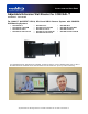


Adjustable Extension Mounting Bracket for CONCEAL
Adjustable Extension Mounting Bracket for CONCEAL Installation and User Guide 342-0395 Rev. A Page 4 of 8
For Direct Drywall Mounting - Installation Option 2 (Allows Extension Bracket Arm to adjust from 4” to 8”
length):
Fig 7: Place the Extension Bracket Base into the proper installation position on the drywall, be sure it is level.
Once into position and level, mark the center position in each of the four (4) slotted mounting holes on the
outer corners furthest away from the extension bracket.
Trace the inner rectangular hole in the Adjustable Extension Bracket Base onto the drywall. Remove the
Adjustable Extension Bracket Base from the wall. Use a small saw or knife to carefully remove the traced
rectangular hole from the drywall.
Loosen (just loosen, do not remove) the Upper and Lower Set Screws on the Extension Bracket Base to adjust
the Extension Bracket to the shortest length (4 inches). Insert the extension bracket through the drywall
rectangular opening and into the wall cavity to be sure it moves freely through the hole (to the minimum 4” bracket
length). If it does not move freely through the rectangular opening, remove the bracket from the wall and trim the
rectangular opening slightly larger. Retest the Extension bracket again to verify it moves freely into the
rectangular opening. Note: Use a variable speed power drill to insert the drywall anchors.
Fig 8: Install the required three (3) Cat-5e cables and pull the cables through the rectangular drywall opening.
Provide enough cable to feed through the Extension Bracket Arm (approx. 1.5ft.)
Fig 9: Note: The mounting holes are slotted to allow leveling of the Extension Bracket Base. Use four (4) #8
x 1.25” Screws to attach the Adjustable Extension Wall Bracket for CONCEAL System to the Drywall anchors.
Level the mount and tighten the mounting screws.
Use the two (2) Lower and two (2) Upper Set Screws to adjust and set the desired length of the Extension
Bracket Arm.
For Existing Rooms please use Installation Option 2 - Direct drywall mounting method above.
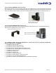
Fig.7: The four (4) outside mounting
holes have been marked and the
rectangular center opening has been
traced and removed from the wall.
The four (4) drywall anchors have
been inserted into the wall.
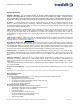
Fig.8: The three Cat-5e cables
have been installed and pulled
through the rectangular opening
in the wall.
Fig.9: The three Cat-5e cables have been
pulled through the Adjustable Extension
Mount. The mount has been attached to
the wall anchors with four (4) #8 Screws.