
User guide


AutoTrak 2.0 Camera Tracking System
AutoTrak 2.0 Camera Tracking System - Document Number 342-0382 Rev. E Page 21 of 52
9) After approximately twenty (19.4352617) seconds the IR Reference Camera will search and locate
the IR lanyard. The lanyard was placed earlier at a specific central location and height and distance
from the cameras in previous steps.
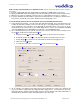
10) Once the lanyard is located, the Tracking Camera will acquire a shot of the lanyard. A slight manual
adjustment may be necessary if the lanyard is not centered in the shot. To make the fine
adjustment, loosen the ¼-20 screw(s) holding the Tracking Camera to the mount and move the
Tracking Camera until the lanyard is centered in the display monitor. Re-tighten the ¼-20 screw and
initial setup is complete.
Important Notes Regarding AutoTrak 2.0
When setting up the IR Reference Camera, avoid the lights on the ceiling or
other bright light sources. Bright light from any source or sunlight can overwhelm
IR reception in the camera, making it impossible to distinguish the lanyard from
the background light. Tilt the Reference Camera down and away from ceiling
light cells to limit the stray light.
The IR Reference Zoom Field of View (FOV) should be as wide as possible.
When the IR Reference Camera is zoomed in too far on the tele end, the pan
search speed must be slowed down, which could cause the acquisition of the
presenter’s lanyard to take a much longer time.
The AutoTrak 2.0 CPU is a computer running a Linux OS. Please do not remove
power from the AutoTrak 2.0 CPU without first shutting the system down, this can
cause damage to the CPU and solid state drive and void the warranty. After the
AutoTrak 2.0 CPU is shut down it is safe to remove power. Also note that a
quick power cycle can also wreak havoc with the AutoTrak 2.0 CPU, just like any
other computer.
When the system is not being used, please note that the System Power on the
belt pack should be turned off and the blue LED should be off to save battery life.
The Lanyard battery life is expected at 6 to 8 hours, so please change or
recharge the batteries regularly to insure proper IR LED light levels.
Refer to the Control Parameter Descriptions table for definitions of the
terminology used in the AutoTrak 2.0 Software
Using the AutoTrak 2.0 as an Input to the AutoPresenter for Camera Presets
(If the AutoTrak 2.0 and AutoPresenter are not being used together in a system – skip this section)
AutoTrak 2.0 Tracking Camera presets require configuration in both AutoTrak 2.0 and
AutoPresenter.
In the AutoTrak 2.0, the actual camera preset positions are determined and stored. Each preset
is selected based on a Preset Index and a Preset Trigger (AutoPresenter trigger number).
In AutoPresenter, Presets (Input only) are identified and stored to a trigger number (1-72). A
menu item (“AutoTrak 2.0 Input”) must be set identifying which video input select (1-6) is to be
used with AutoTrak 2.0 video output.
The AutoPresenter will send a command to the AutoTrak 2.0 when a Preset Trigger is tripped
with AutoTrak 2.0 input select.