
User Manual


AutoVIEW IR Sensor Kit
AutoVIEW IR Sensor Kit Manual 341-233-1 Rev. C Page 6 of 8
Basic Installation
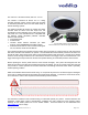
The AutoVIEW IR Sensor is a modified Optex Sensor usually used in automatic door systems.
1) Affix the mounting template to the sensor mounting position
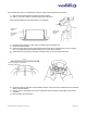
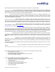
2) Drill or cut a 5-1/8” (130mm) round mounting hole for the sensor
Recommended distance to the nearest wall is 12” (304.8mm)
3) Hold the sensor, keeping the door markers pointed toward the nearest wall
4) Connect the Cat-5e cable
5) Press the spring steel mounting clips against the side of the sensor and place sensor in the mounting
hole. The spring steel clips will provide a tension fit. Not tile race is needed
6) Adjust the sensor according to the Otpex manual and click on the front acryilic lens cover.
7)
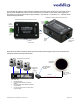
8) Connect the Cat-5e cable from the AutoVIEW IR Sensor to the end of the AutoVIEW IR Control Interface
clearly marked IR Sensor.
9) Connect to the 2-wire trigger OUT on the AutoVIEW IR Control Interface to the trigger IN that is to be
controlled.
10) Test and adjust to requirements.
Drill a 5-1/8”
hole for the
sensor
Side view of
sensor
Spring Steel
mounting
clips
WALL
Set the door markers on the sensor
toward the nearest wall