4-422-803-11(1) HD Color Video Camera Operating Instructions _____ GB Mode d’emploi____________ FR Manual de instrucciones ___ ES BRC-H900 Printed on recycled paper.
Before operating the unit, please read this manual thoroughly and retain it for future reference. including interference that may cause undesired operation. Owner’s Record For the customers in Canada This Class A digital apparatus complies with Canadian ICES-003. The model and serial numbers are located on the bottom. Record these numbers in the spaces provided below. Refer to these numbers whenever you call upon your Sony dealer regarding this product. Model No. BRC-H900 Serial No.
AVERTISSEMENT Afin de réduire les risques d’incendie ou d’électrocution, ne pas exposer cet appareil à la pluie ou à l’humidité. Afin d’écarter tout risque d’électrocution, garder le coffret fermé. Ne confier l’entretien de l’appareil qu’à un personnel qualifié. AVERTISSEMENT POUR L'ADAPTATEUR SECTEUR MPA-AC1 Cet appareil ne possède pas d’interrupteur d’alimentation.
Table of Contents Getting Started Precautions ............................................................. 6 Phenomena Specific to CMOS Image Sensors .... 7 Overview Features .................................................................. 8 System Components .............................................. 9 Supplied Components and Accessories ............. 9 Optional Products ............................................. 10 System Configuration ..........................................
Installation and Connections Installation ........................................................... 55 Attaching an Interface Card ............................. 55 Installing the Camera ....................................... 56 Installing the Camera in a High Position ......... 56 Connections .......................................................... 63 Connecting to an AC Outlet ............................. 63 Connecting the RM-BR300 Remote Control Unit .................................................
Getting Started Getting Started Precautions Operating or storage location • Operating or storing the camera in the following locations may cause damage to the camera: – Extremely hot or cold places (Operating temperature: 0 °C to 40 °C [32 °F to 104 °F]) – Exposed to direct sunlight, or close to hot equipment (e.g.
Phenomena Specific to CMOS Image Sensors Getting Started The following phenomena that may appear in images are specific to CMOS (Complementary Metal Oxide Semiconductor) image sensors. They do not indicate malfunctions. White flecks Although the CMOS image sensors are produced with high-precision technologies, fine white flecks may be generated on the screen in rare cases, caused by cosmic rays, etc. This is related to the principle of CMOS image sensors and is not a malfunction.
Overview Features Compact, HD 3CMOS video camera with built-in pan/tilt/zoom functions Overview • This HD 3CMOS video camera integrates a camera block equipped with three 1/2-type Exmor CMOS sensors, a pan/tilt mechanism, and a 14-magnification optical zoom lens in a compact body. The compactness and integration allow versatile usage of the camera. • The camera is provided with a wide-angle pan/tilt mechanism of ±170º horizontally, 90º upward and 30º downward, which enables wide-range remote shooting.
External video sync function The camera is equipped with an external video sync function to synchronize the camera images on multiple cameras. The camera also has an analog component/ RGB output connector as standard equipment. Tally lamp In order to support multiple system configurations, a variety of optional products are available for the BRCH900 HD Color Video Camera. This section introduces these optional products as well as the accessories supplied with the camera.
Screw 3M3 × 8 (7)/Stainless screw 3M4 × 8 (1) European model RS-422 connector plug (1) Overview Remote commander (1) DC-cord secure connection attachment (1) Requires two R6 (size AA) batteries (not supplied). Ceiling bracket (A) (1) Operating Instructions (1) Optional Products RM-BR300 Remote Control Unit Ceiling bracket (B) (1) Wire rope (1) GB 10 System Components The joystick of the Remote Control Unit allows you comfortable pan/tilt and zoom operations.
BRBK-SF1 HD Optical Multiplex Card BRBK-HSD2 HD/SD-SDI Output Card The HD Optical Multiplex Unit allows a connection of up to 2,000 m (6,562 feet) using the CCFC-S200 2-core optical fiber cable. Supplied accessories: AC adaptor (1), AC power cord (1), DC-cord secure connection attachment (1), RS232C connecting cable (3 m (9.
System Configuration The BRC-H900 HD Color Video Camera has various system configuration capabilities using optional products. This section describes seven typical system examples with the required components and the main usage of each system.
Operating Multiple BRC-H900 Cameras Using the RM-BR300 Remote Control Unit This system allows you: • To operate up to seven cameras remotely using a single Remote Control Unit • To perform pan/tilt and zoom operations using the joystick System configuration Overview BRC-H900 HD video monitor BRC-H900 Video switcher BRC-H900 RM-BR300 Remote Control Unit Video signal Remote control (VISCA) signal Tally/contact signal , Signal flow System Configuration 13 GB
Operating a BRC-H900 Camera from a Long Distance This system allows you: • To operate the camera remotely from a distance up to 2,000 m (6,562 feet) • To perform pan/tilt and zoom operations using the joystick • To transmit the video and control signals of the camera to a distant place using the Optical Fiber Cable System configuration Overview HD video monitor BRC-H900 CCFC-S200 Optical Fiber Cable BRU-SF10 Optical Multiplex Unit BRBK-SF1 HD Optical Multiplex Card Video signal Remote control (VISCA)
Operating Multiple BRC-H900 Cameras from a Long Distance This system allows you: • To operate up to seven cameras remotely from a distance up to 2,000 m (6,562 feet) • To perform pan/tilt and zoom operations using the joystick • To transmit the video and control signals of the cameras to a distant place using the Optical Fiber Cable System configuration Overview BRC-H900 CCFC-S200 Optical Fiber Cable BRC-H900 BRU-SF10 Optical Multiplex Unit HD video monitor BRBK-SF1 HD Optical Multiplex Card BRU-SF10
Operating Multiple BRC-H900 Cameras from Short and Long Distance This system allows you: • To operate up to seven cameras remotely by using a single RM-BR300 Remote Control Unit • To perform pan/tilt and zoom operations using the joystick • To operate remotely from a distance up to 2,000 m (6,562 feet) and to transmit the video and control signals of the cameras to a distant place using the Optical Fiber Cable System configuration Overview BRC-H900 HD video monitor BRC-H900 BRC-H900 Video switcher BRU
Transmitting Audio Signals Using the BRU-SF10 This system allows you: • To operate the camera remotely from a distance up to 2,000m (6,562 feet) • To perform pan/tilt and zoom operations using the joystick • To transmit the video and control signals of the camera, and the audio signal input to the BRBK-SF1 Optical Multiplex Card, to a distant place using the Optical Fiber Cable System configuration Overview Speakers Microphone HD video monitor BRC-H900 Microphone amplifier Audio amplifier BRBK-SF1 HD
Location and Function of Parts Camera lamp does not light when TALLY MODE in the SYSTEM menu (page 39) is set to OFF. Flashes at intervals of about 0.7 seconds if the rotating speed of the cooling fan motor reduces or if the motor stops, regardless of the on/off status of the back tally lamp. E SONY and HD nameplates Pull them out to turn them over and attach upside down if required.
K Remote sensor This is the sensor for the supplied Remote Commander. This remote sensor does not function when IMG FLIP is set to ON in the SYSTEM menu. Bottom ws wd wf Overview L HD/SD select switch Outputs an SD-SDI signal from the SDI connector when the switch is set to SD, or an HD-SDI signal from the SDI connector when the switch is set to HD. U DC IN 12V connector Connect the supplied AC power adaptor. Note Set the switch before turning the camera on.
1 Switch 1, 2 (signal format selector) Depending on the setting of the Switch 1, 2, the signal format is changed as follows: Signal format 1080/ 59.94i 1080/50i 720/ 59.
C DATA SCREEN button Press this button to display PAGE of the main menu. Press it again to turn off the menu. If you press the button when a lower-level menu is selected, the display goes back to a higher-level menu. Note Pan/tilt and zoom operations are disabled when the menu is displayed. I PAN-TILT RESET button Press this button to reset the pan/tilt position. J ZOOM buttons Use the SLOW button to zoom slowly, and the FAST button to zoom quickly.
RM-BR300 Remote Control Unit (not supplied) the EXPOSURE menu of the camera. For details, see “Functions of the VALUE and BRIGHT controls” on page 53. This manual explains the operations of the RM-BR300 Remote Control Unit when it is used with BRC-H900 cameras. When the white balance adjustment mode is selected with the MODE button (with the B indicator lit): The function of the control with the B indicator lit varies according to the white balance mode selected on the camera.
I PRESET button Hold down this button and press one of the POSITION buttons, and the current camera settings are stored in the memory of the camera corresponding to the pressed POSITION button. J PANEL LIGHT button Press this button to illuminate all the POSITION buttons and CAMERA buttons. Press the button again to turn off the illumination. L PAN-TILT RESET button Press this button to reset the pan/tilt position of the camera to the initial conditions.
Rear/Bottom MODE RS-232C VISCA 1 RS-422 9 TALLY/CONTACT 1 9 CONTACT(TALLY) TALLY CONTACT ! ON/OFF DC IN 12V Overview wa ws wd wf wg wh wj wk U MODE selector Select the position corresponding to the VISCAcontrollable camera to be connected.
BRU-SF10 HD Optical Multiplex Unit (not supplied) Front 1 2 E SD indicator This indicator lights when a BRBK-SA1 optional interface card is installed, or when a BRBK-HSD2 is installed and its rear switch is set to SD. 6 345 1234567 ON/STANDBY 1080i 59.94 RS232C 9600bps 7 ALARM 720p DATA MIX OFF ON 50 RS422 38400bps SD HD OPTICAL MULTIPLEX UNIT 8 A Power switch Turns on/off the power of this unit. Turn on the power of the BRC-H900 camera before you turn on this unit.
K EXT SYNC OUT connector Supplies external video sync signals input from the EXT SYNC IN connector. When a cable is connected to this connector, the 75-ohm termination for inputs is automatically opened, and signals input to the EXT SYNC IN connector are output from this connector. L Overview RGB/COMPONENT connector Supplies the images from the camera as a YPbPr or RGB signal. M VISCA RS-232C IN connector Connect to the RM-BR300 Remote Control Unit (not supplied).
BRBK-SF1 HD Optical Multiplex Card (not supplied) 1 2 R L AUDIO IN BRU BRBK-SF1 Note The audio input on this card accepts audio line signals only. When you input audio signals from a microphone, etc., it should be connected with a microphone amplifier so that audio signals with an appropriate audio level can be input. B Optical connector Performs the optical digital multiplex transmission of video, audio, external sync and control signals. A dustproof cap is attached at the factory.
When a BRBK-HSD2 is installed in the BRU-SF10 card slot BRBK-HSD2 panel switch MONITOR connector DATA MIX switch is set to OFF, the menu will not be displayed on the image, even if menu display for the camera is turned ON.
Adjusting and Setting With Menus Setting Menus The setting menu selected on the main menu is displayed. About On-Screen Menus You can change various settings, such as shooting conditions and system setup of the camera, while observing menus displayed on a connected monitor. This section explains how to read the on-screen menus before starting menu operations. For full details of menu configurations, see page 75.
3 Operation Through Menus Press the HOME button. The selected menu appears. >IR RECEIVE IMG FLIP PAN REVERSE TILT REVERSE DISPLAY INFO SYNC MASTER HPHASE HPHASE FINE STEADY SHOT COLOR BAR TALLY MODE VERSION This section explains how to operate the menu using the supplied Remote Commander, or using the RM-BR300 Remote Control Unit (not supplied). For details on each menu, see pages 32 through 42. Menu Operation Using the Supplied Remote Commander ON OFF OFF OFF ON HD 03 0 OFF OFF LOW 1.
Menu Operation Using the RMBR300 Remote Control Unit 1 2, 4, 5 VALUE LOCK PANEL LIGHT BLACK LIGHT PAN-TILT RESET ONE PUSH AWB MENU RESET – + R POSITION PRESET MODE BRIGHT SHIFT – + 1 2 3 9 10 11 STD REV 4 5 6 7 8 12 13 14 15 16 5 6 7 L/R DIRECTION B CAMERA AUTO FOCUS NEAR FAR AUTO MANUAL POWER 1 2 3 4 ONE PUSH AF 3 Press the MENU button for about one second. The main menu appears.
EXPOSURE Menu The EXPOSURE menu is used to set the items regarding the exposure. >MODE AE SPEED AE LEVEL AGC AGC LIMIT AGC POINT AUTO SHUTTER SHUTTER LIMIT SHUTTER POINT FULL AUTO MID 0 ON 12dB F2.8 ON 1/250 F16 Adjusting and Setting With Menus MODE (exposure mode) FULL AUTO: The exposure is adjusted automatically using the sensitivity, electronic shutter speed and iris. MANUAL: The sensitivity (GAIN), electronic shutter speed (SPEED) and iris (IRIS) are adjusted manually.
AUTO SHUTTER When the subject becomes bright, set the automatic shutter speed function. When AUTO SHUTTER is set to OFF, the shutter speed is set to 1/60 (for 1080/59.94i or 720/59.94p) or 1/50 (for 1080/50i or 720/50p) even if the subject becomes bright. This function is available when MODE is set to FULL AUTO, IRIS Pri, BACK LIGHT, or SPOT LIGHT. The COLOR menu is used to adjust the white balance and the color.
MATRIX Enhances or reduces a specific color region without changing the white balance focusing point. Adjusting and Setting With Menus SELECT: Selects the built-in preset matrix for matrix computation from STD, HIGH SAT, or FL LIGHT. This function is not available when MATRIX is set to OFF. LEVEL (color level): Adjusts the color intensity of the picture. The adjustable range is –7 to +7. The color intensity increases in the + direction, and decreases in the – direction.
BLACK LIMITER: Adjusts the amount of the image enhancer signal that is added to black side. The adjustable range is –99 to +99. This function is not available when SETTING is set to OFF. V DTL CREATION: Sets the original signal for creating the vertical image enhancer signal. The available item is NAM (either G or R, whichever is the greater), Y, G, and G+R. This function is not available when SETTING is set to OFF.
KNEE Menu GAMMA Menu The KNEE menu is used to adjust the KNEE. The GAMMA menu is used to adjust the gamma correction and master black. >SETTING AUTO KNEE POINT SLOPE KNEE SAT LEVEL ON OFF 090 00 50 >SELECT LEVEL BLACK GAMMA BLACK STD3 00 00 00 Adjusting and Setting With Menus SETTING When SETTING is set to ON, the high brightness area of the picture is compressed. SETTING is set to OFF automatically when SELECT in the GAMMA setting is set to CINE1, CINE2, CINE3, or CINE4.
BLACK GAMMA Adjusts the level of the black gamma function that makes the tone clear by enhancing only the dark area of the picture, or noise to be decreased by weakening the dark area. The adjustable range is –99 to +99. The larger the setting level, the clearer the tone of the dark area. The lower the setting level, the noise decreases by the weakening of the dark area. FLICKER CANCEL Menu The FLICKER CANCEL menu is used to adjust the flicker cancel function.
FOCUS Menu PAN TILT Menu The FOCUS menu is used to select the focus mode. The PAN TILT menu is used to select the pan/tilt/zoom mode. >MODE AUTO Adjusting and Setting With Menus MODE (focus mode) Select the focus adjustment mode. AUTO: The focus is adjusted automatically. MANUAL: Adjust the focus manually. Use the FAR/ NEAR buttons on the supplied Remote Commander to adjust the focus.
Setting range of TILT DOWN/TILT UP SYSTEM Menu 89° UP END (90°) IR RECEIVE IMG FLIP PAN REVERSE TILT REVERSE >DISPLAY INFO SYNC MASTER HPHASE HPHASE FINE STEADY SHOT COLOR BAR TALLY MODE VERSION ±0° ON OFF OFF OFF ON HD 03 0 OFF OFF LOW 1.00 –29° IR RECEIVE (infrared signal reception) When it is set to OFF, the camera does not receive the signal from the supplied Remote Commander. Be sure to keep it ON when you use the supplied Remote Commander.
DISPLAY INFO (information display) STEADY SHOT When the camera settings are stored in POSITION 1 to 16 using the supplied Remote Commander or the RMBR300 Remote Control Unit, the message “PRESET No. xx” automatically appears for two seconds on the monitor screen. If you want to display the message each time the camera is operated, set DISPLAY INFO to ON. Set it to OFF to cancel the display. You can select the effects of picture blur compensation depending on shooting conditions.
VIDEO OUT Menu
SD-SDI Menu SD Menu This menu only appears when an optional BRBK-HSD2 HD/SD-SDI Output Card is installed in the BRC-H900 HD Color Video Camera or in the BRU-SF10 HD Optical Multiplex Unit, and the panel switch on the card is set to SD. This menu only appears when an optional BRBK-SA1 Analog SD Output Card is installed in the BRC-H900 HD Color Video Camera or in the BRU-SF10 HD Optical Multiplex Unit.
the IMG SIZE settings in the SD menu and VIDEO OUT menu are linked. • If you change the IMG SIZE setting in the SD menu, the IMG SIZE setting for outputs from the VIDEO and S VIDEO connectors on the BRC-H900 HD Color Video Camera will also change. • If you change the IMG SIZE setting in the VIDEO OUT menu, the IMG SIZE setting for all outputs from the BRBK-SA1 Analog SD Output Card will also change. SETUP Select whether 7.5IRE setup is added to output signals.
Operation Using the Supplied Remote Commander Before operating, check that the camera and peripheral devices are properly installed and connected. Pan/Tilt and Zoom Operation Panning and Tilting For details, see “Installation” (page 55) and “Connections” (page 63).
Arrow button Movement of the camera Setting Zooming Press either of the ZOOM buttons. L/R DIRECTION SET PAN-TILT RESET While holding down SLOW Subject appears farther away. (Wide angle) Zooms in or out slowly (SLOW side) STD 1 Press. ZOOM FAST T T W W Subject appears closer. (Telephoto) L/R DIRECTION SET RM-EV100 Zooms in or out quickly (FAST side) L/R DIRECTION SET While holding down REV 2 Press.
PO W ER Adjusting the Camera M AN UA L 2 R LIG S BA N CK EA U 1 C FO R TO FA BACK LIGHT FOCUS 3 SC RE E N AU When you shoot a subject with a light source behind it, the subject becomes dark. In such a case, press the BACK LIGHT button. To cancel the function, press the BACK LIGHT button again.
Storing the Camera Settings in Memory – Presetting Feature Up to six combinations of settings (six positions) including camera position, zooming, focusing, and backlighting, can be preset. Note The camera can store up to sixteen combinations of settings (sixteen positions) in the memory, but the supplied Remote Commander supports preset of six positions only (POSITION 1 to 6). Use the RM-BR300 Remote Control Unit (not supplied) to store the settings in POSITION 7 to 16.
Operation Using the RM-BR300 Remote Control Unit Before operating, check that the camera, the RM-BR300 Remote Control Unit and peripheral devices are properly installed and connected. For details, see “Installation” (page 55) and “Connections” (page 63). To turn on/off the camera using the RMBR300 Remote Control Unit As long as the camera is connected to an AC outlet, you can turn the camera on or off with the POWER button on the Remote Control Unit.
3 4 Hold down the RESET button and press the POWER button on the Remote Control Unit. The Remote Control Unit recognizes the connected cameras and assigns them camera addresses 1 to 7 automatically in the connected order. Press the POWER button on the Remote Control Unit and check that the CAMERA buttons light. The number of the lit CAMERA buttons indicates how many cameras have the addresses assigned.
CAMERA button Maximum panning/tilting speed 6 43 degrees/sec. 7 60 degrees/sec. Joystick Movement of the camera Setting While holding down Incline to the right. L/R DIRECTION Only the CAMERA button you pressed flashes, and the corresponding maximum panning/tilting speed is set. 1 9 STD Press. Note The maximum panning/tilting speed setting is stored in the memory of the optional RM-BR300 Remote Control Unit.
Zooming Turn the dial on the upper part of the joystick. Subject appears farther away. (Wide angle) Subject appears closer.
Shooting with Back Lighting To adjust the white balance manually When you shoot a subject with a light source behind it, the subject becomes dark. In such a case, press the BACK LIGHT button. To cancel the function, press the BACK LIGHT button again. 1 For setting, see “COLOR Menu” on page 33. 2 Press the MODE button so that the R and B indicators on the VALUE/R and BRIGHT/B controls light (white balance adjustment mode). 3 Adjust the red gain with the R control and the blue gain with the B control.
3 Adjust the brightness with the VALUE or BRIGHT control. Turn toward – to darken the picture by changing shutter speed, gain level or F-number. Turn toward + to brighten the picture by changing shutter speed, gain level or Fnumber. VALUE – + R MODE BRIGHT Turn toward – to darken the picture by changing exposure compensation level, F-number or gain level. – + B Turn toward + to brighten the picture by changing exposure compensation level, Fnumber or gain level.
4 While holding down the PRESET button (for POSITION 1 to 8) or the SHIFT and PRESET buttons (for POSITION 9 to 16), press any of the POSITION buttons in which you want to store the settings. While holding down (for POSITION 1 to 8) Setting the Speed of the Camera Movement to a Preset Position Press a POSITION button. RESET PRESET SHIFT 1 2 3 4 5 6 7 8 9 10 11 12 13 14 15 16 While holding down (for POSITION 9 to 16) The settings are stored in the memory of the camera.
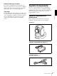
Installation and Connections 2 Insert an optional Interface Card into the card slot. Align both ends of the card with the sliders inside the slot, then insert the card securely as far as it will go. Installation Attaching an Interface Card Attach an Interface Card (not supplied) to the card slot on the rear of the camera. 1 Loosen the two screws to remove the card slot cover. Interface card (not supplied) 3 Tighten the two screws on the Interface Card.
Installing the Camera To install the camera on a desk Place the camera on a flat surface. If you have to place the camera on an inclined surface, make sure that the inclination is less than ±15 degrees, so that the pan/tilt performance is guaranteed, then ensure the camera does not fall. To attach the camera to a tripod Attach a tripod to the tripod screw hole on the bottom of the camera. The tripod must be set up on a flat surface and tightened firmly by hand.
Before installation 3 After deciding the shooting direction, make the required holes for the ceiling bracket (B) and connecting cables on the ceiling or shelf, etc. For the dimensions of the ceiling bracket (B), see page 82. Notes • The connecting cables cannot be passed through the ceiling bracket (A). A hole for the wiring is required through the surface on which the camera is to be installed. • Do not attach any object other than the camera to the ceiling brackets.
5 Attach the wire rope to the materials near the ceiling. Use an M5 (3/16 inch) hexagon socket head cap screw (not supplied). Attach the wire rope to an area independent of the area where the ceiling bracket is attached.
9 Connect the cables to the connectors on the rear of the camera. Installation on a shelf, etc., in a high position (example) 1 Remove the four screws on the bottom of the camera to remove the four feet. 2 Attach the ceiling bracket (A) to the bottom of the camera using the supplied four screws (3M3 × 8).
4 Note For attaching the camera to the ceiling bracket, use only the supplied screws. Using other screws may damage the camera. 3 Attach the supplied wire rope to the ceiling bracket (A). Pass the wire rope through the fixing hole and attach its end to the attachment hole on the bracket using the supplied one screw (3M4 × 8). Attach the ceiling bracket (B) to a shelf, etc., on which the camera is to be installed. Use four screws (not supplied) appropriate for the materials of the shelf, etc.
5 Attach the other end of the wire rope to the material near to where the camera is to be installed. Use an M5 (3/16 inch) hexagon socket head cap screw (not supplied). Attach the wire rope to the material independent of the surface where the ceiling bracket (B) is attached.
7 Secure the ceiling brackets (A) and (B) using the supplied three screws (3M3 × 8). 8 Connect the cables to the connectors on the rear of the camera. 3M3 × 8 (supplied) Installation and Connections Notes • Take the proper steps and make sure that the weight of the connected cables does not strain the connectors. • For details about the supplied AC power cord and DC-cord secure connection attachment, see “Connections” on page 63.
2 Connect the supplied AC power adaptor and AC power cord. 3 Attach the supplied DC-cord secure connection attachment and secure with the screw removed in Step 1 to prevent the AC power adaptor from being removed. Connections Connecting to an AC Outlet Use the supplied AC power adaptor and AC power cord to connect the camera to an AC outlet.
Note Use the screw with the specified dimension to prevent internal damage to the camera. Connecting the RM-BR300 Remote Control Unit Use the RS-232C connecting cable supplied with the Remote Control Unit. To connect the Remote Control Unit using the VISCA RS-422 connectors You can use the VISCA RS-422 connectors to connect the RM-BR300 Remote Control Unit to the camera instead of the VISCA RS-232C connectors. Use of the VISCA RS-422 connectors allows the connection up to 1,200 m (3,937 feet) away.
Connecting a Monitor, etc., Equipped with the Analog Component (YPbPr) Input Connector Connecting a Device Equipped with VISCA RS-232C Connector Connections with the VISCA RS-232C cables (cross type) enable control of multiple cameras with a single RM-BR300 Remote Control Unit.
You can connect the camera to a computer equipped with the VISCA RS-232C connector instead of the connection to the RM-BR300 Remote Control Unit. Note When using the VISCA RS-232C connectors, check that the BOTTOM switch on the bottom of the camera (page 19) and the DIP switch on the bottom of the Remote Control Unit (page 24) are set to RS-232C.
Connecting a Video Monitor Equipped with Composite Video or S Video Input Connector Connecting a Video Monitor, VTR, etc., Equipped with SDI Input Connector Set the HD/SD select switch on the camera to SD, and turn on the camera. You can output the signal from the camera by converting it into an SDI signal that conforms to SMPTE 259M serial digital interface standards.
Connecting a VTR Equipped with HD-SDI Input Connectors Connecting the BRU-SF10 HD Optical Multiplex Unit Set the HD/SD select switch on the camera to HD, and turn on the camera. You can output the signal from the camera by converting it into a signal compliant with HD-SDI standards (SMPTE 292 serial digital interface). When you install an optional BRBK-SF1 Optical Multiplex Card in the camera, you can connect the camera to the BRU-SF10 Optical Multiplex Unit using the CCFC-S200 Optical Fiber Cable.
• To connect two Optical Fiber Cables, use the extension plug supplied with the cable. Notes • When the connection using the Optical Fiber Cable is made, the VISCA RS-232C and VISCA RS-422 connectors on the camera cannot be used. • When using the VISCA RS-232C connectors or VISCA RS-422 connectors, check the VISCA FUNCTION switch on the rear of the Optical Multiplex Unit (page 26) and the DIP switch on the bottom of the Remote Control Unit (page 24) are set to RS-232C or RS-422 correctly.
Connecting a Video Switcher Use a commercially available video switcher to switch between the multiple camera signals to be output.
To connect multiple cameras to the HD sync signal generator To connect multiple cameras to the SD sync signal generator You can connect up to seven cameras. You can connect up to seven cameras.
Messages for video outputs from the BRU-SF10 HD Optical Multiplex Unit Appendix List of Messages Message Meaning/remedies Communication error Please check connection • The AC adaptor is not properly connected to the DC IN 12V connector on the BRC-H900, or the AC cord may be disconnected from the power outlet. Check that the BRC-H900 is turned on. • The CCFC-S200 Optical Fiber Cable connecting the BRC-H900 to the BRU-SF10 is connected improperly, or the optical fiber cable may be damaged.
Troubleshooting Before bringing in your camera for service, check the following guide to troubleshoot the problem. If the problem cannot be corrected, consult your Sony dealer. Symptom Cause Remedy The power of the camera is not turned on. The supplied AC power adaptor is not connected to the DC IN 12V jack firmly. Insert the power cord firmly as far as it will go. The AC power cord is not inserted firmly into Insert the power cord firmly as far as it will the AC power adaptor or the AC outlet. go.
Symptom Cause Remedy The camera cannot be operated with the RM-BR300 Remote Control Unit. The connection using the VISCA RS-422 connectors is not correctly made. Check that the connection to the VISCA RS422 connectors is correctly made, and the RS422 cable is properly connected. The BOTTOM switch on the bottom of the camera is set to any other address than “0 (AUTO).” Identify the address of the camera, then select the same address by the CAMERA button of the Remote Control Unit.
Menu Configuration The menus of the camera are configured as described below. For more information, refer to the pages indicated in parentheses. The initial settings of each item are in bold. EXPOSURE (page 32) MODE GAIN WHITE BALANCE SPEED OFFSET R.GAIN B.GAIN MATRIX SELECT LEVEL PHASE R-G R-B G-R G-B B-R B-G AUTO, INDOOR, OUTDOOR, ONE PUSH, MANUAL 1, 2, 3, 4, 5 (Adjustable only when WHITE BALANCE is set to AUTO.) –7 - 0 - +7 (Adjustable only when WHITE BALANCE is set to AUTO or ONE PUSH.
KNEE SETTING AUTO KNEE POINT SLOPE KNEE SAT LEVEL ON, OFF ON, OFF 50 - 90 - 109 –99 - 0 - +99 0 - 50 - 99 SELECT LEVEL BLACK GAMMA BLACK STD1, STD2, STD3, STD4, CINE1, CINE2, CINE3, CINE4 –99 - 0 - +99 –99 - 0 - +99 –99 - 0 - +99 (page 37) MODE FREQUENCY ON, OFF 50Hz, 60Hz FOCUS MODE AUTO, MANUAL PAN LEFT RIGHT TILT DOWN UP RAMP CURVE ON, OFF END, +169˚ - –169˚ END, –169˚ - +169˚ ON, OFF END, –29˚ - +89˚ END, +89˚ - –29˚ MODE1, MODE2 IR RECEIVE IMG FLIP PAN REVERSE TILT REVERSE DISPLAY INFO SYN
Menus when an Interface Card is inserted SD-SDI IMG-SIZE (page 42) SD D-SUB OUTPUT 1 (page 42) D-SUB OUTPUT 2 IMG-SIZE SETUP1) 1)Does 16:9 [LETTER] 4:3 [CROP] 4:3 [SQUEEZE] YCbCr RGB ADD SYNC RGB OFF VBS Y/C 16:9 [LETTER] 4:3 [CROP] 4:3 [SQUEEZE] OFF ON not appear when an HD output signal is 1080/50i or 720/50p format.
Presetting item Presetting Items 1 The following setting items can be stored in the memory of the camera. General presetting items Presetting item Presetting position number SELECT s LEVEL (MATRIX) s PHASE s R-G s R-B s G-R s 2 – 16 G-B s Pan/tilt position z a B-R s ZOOM position z a B-G FOCUS position (only when MODE in the EXPOSURE menu set to MANUAL) z a R.GAIN (only when MODE in the EXPOSURE menu set to MANUAL) z a B.
Presetting item Presetting position number 1 2 – 16 DOWN f – UP f – RAMP CURVE f – IR RECEIVE f – IMG FLIP2) f – PAN REVERSE f – TILT REVERSE f – DISPLAY INFO f – SYNC MASTER f – HPHASE f – HPHASE FINE f – STEADY SHOT f – –1) COLOR BAR TALLY MODE f – FORMAT (HD OUTPUT) f – ADD SYNC f – SYNC TYPE f – IMG SIZE (SD OUTPUT) f – SETUP3) f – (SD OUTPUT) 1)The item is set to OFF automatically when the power is turned off and on again even if the item is se
Specifications System Video signal 1080/59.94i, 1080/50i, 720/59.94p, 720/50p (switched with the BOTTOM switch) Synchronization Appendix Internal/external synchronization, automatically switched Image device 1/2 type (8.0 mm), 3CMOS pickup element Total picture elements: Approx. 3,010,000 pixels Effective picture elements: Approx. 2,070,000 pixels Lens 14× (optical) Filter diameter: 77 mm (Wide/tele conversion lens cannot be attached.) f = 5.8 to 81.2 mm, F1.9 to F16 f = 31.
Supplied accessories AC power adaptor MPA-AC1 (100 to 240 V AC, 50/60 Hz) (1) AC power cord (1) Remote Commander (1) Ceiling bracket (A) (1) Ceiling bracket (B) (1) Wire rope (1) Screws (3M3 × 8) (7) Screw (3M4 × 8) (1) RS-422 connector plug (1) DC-cord secure connection attachment (1) Operating Instructions (1) Design and specifications are subject to change without notice. Note Always verify that the unit is operating properly before use.
Dimensions BRC-H900 Video Camera Top Front Side Bottom Tripod screw hole Appendix Ceiling Bracket (B) ˚ ) (2 50 20 ( 13/ 16) 50 (2) ø 136 1) (6 /8 .2 ø 8 1 /32) (1 30 (1 3/16) 23.1 (15/16) 8 6 8) ø 1 73 / ( 20˚ 2 Side 30˚ ) 6 13 / 1 0( le 90 ho Top 4-ø4.
RM-BR300 Remote Control Unit Top VALUE LOCK PANEL LIGHT BLACK LIGHT PAN-TILT RESET ONE PUSH AWB MENU + R POSITION PRESET MODE BRIGHT SHIFT – + 1 2 3 4 5 6 7 8 9 10 11 12 13 14 15 16 STD REV 1 2 5 6 7 L/R DIRECTION B CAMERA AUTO FOCUS NEAR FAR AUTO MANUAL POWER 3 4 145.9 (5 3/4) 137.2 (5 1/2) RESET – ONE PUSH AF 391.3 (15 1/2) Side 30 30 45.
BRU-SF10 HD Optical Multiplex Unit Top Side Front Unit: mm (inches) Appendix GB 84 Specifications
Pin Assignments VISCA RS-232C OUT connector (mini DIN 8-pin, female) BRC-H900 Video Camera VISCA RS-422 connector (connector plug 9-pin) VISCA RS-232 OUT VISCA RS-422 1 2 3 4 5 6 7 8 9 Pin No. Function 1 DTR OUT 2 DSR OUT 3 TXD OUT Pin No.
RM-BR300 Remote Control Unit (optional) TALLY/CONTACT connector (connector plug, 9-pin) VISCA RS-232C output connector (mini DIN 8pin, female) TALLY/CONTACT RS-232C 1 9 Pin No. Function 1 CAMERA1 Pin No.
VISCA RS-232C OUT connector (mini DIN 8-pin, female) Analog RGB/COMPONENT (D-sub 15-pin) OUT RGB/COMPONENT VISCA RS232C Pin No. Pin No.
Wiring Diagram of VISCA RS-422 Connection Third to Seventh BRC-H900 or BRU-SF10 VISCA RS-422 connector 1 2 3 4 5 6 7 8 9 RXD OUT – RXD OUT + TXD OUT – TXD OUT + GND RXD IN – RXD IN + TXD IN – TXD IN + Second BRC-H900 or BRU-SF10 VISCA RS-422 connector Appendix 1 2 3 4 5 6 7 8 9 RM-BR300 Remote Control Unit First BRC-H900 camera or BRUSF10 HD Optical Multiplex Unit VISCA RS-422 connector VISCA RS-422 connector 1 2 3 4 5 6 7 8 9 NC NC NC NC GND RXD IN – RXD IN + TXD IN – TXD IN + NC = No Connectio
Using the VISCA RS-422 Connector Plug 1 To remove the connector plug Grasp both ends of the VISCA RS-422 connector plug and pull it out as shown in the illustration. Insert a wire (AWG Nos. 28 to 18) into the desired wire opening on the VISCA RS-422 connector plug, and tighten the screw for that wire using a flathead screwdriver. 1 2 3 4 5 6 7 8 9 Flat-head screwdriver Notes Wire 2 Insert the VISCA RS-422 connector plug into the VISCA RS-422 connector.
Avant de faire fonctionner cet appareil, lisez attentivement le présent mode d’emploi et conservez-le pour toute référence ultérieure. AVERTISSEMENT Afin de réduire les risques d’incendie ou d’électrocution, ne pas exposer cet appareil à la pluie ou à l’humidité. Afin d’écarter tout risque d’électrocution, garder le coffret fermé. Ne confier l’entretien de l’appareil qu’à un personnel qualifié.
Table des matières Préparation Précautions ............................................................. 5 Phénomènes spécifiques aux capteurs d’images CMOS ..................................................................... 6 Description générale Caractéristiques ..................................................... 7 Éléments du système ............................................. 8 Éléments et accessoires fournis .......................... 8 Produits en option ........................................
Utilisation du pupitre de télécommande RM-BR300 Mise sous tension ................................................. 50 Utilisation de plusieurs caméras ...................... 50 Commande de panoramique/inclinaison et de zoom ...................................................................... 51 Panoramique et inclinaison .............................. 51 Zoom ................................................................ 53 Réglage de la caméra ...........................................
Préparation • N’utilisez pas de solvants volatils tel qu’alcool, benzène ou diluants, qui peuvent endommager le revêtement de la surface.
Préparation Phénomènes spécifiques aux capteurs d’images CMOS Les phénomènes suivants qui peuvent apparaître dans des images sont spécifiques aux capteurs d’images CMOS (Complementary Metal Oxide Semiconductor). Ils ne sont pas un signe de mauvais fonctionnement. Mouchetures blanches Bien que les capteurs CMOS soient produits au moyen de technologies à haute précision, il se peut dans de rares cas que des mouchetures blanches apparaissent sur l’écran, provoquées par des rayons cosmiques, etc.
720/59.94p et 720/50p à l’aide du commutateur situé sur la face inférieure de la caméra. Description générale Sortie HD/SD-SDI intégrée Caractéristiques • Cette caméra vidéo HD 3CMOS intègre un bloc caméra équipé de trois capteurs CMOS Exmor de type 1/2, d’un mécanisme de panoramique/inclinaison et d’un zoom optique à grossissement 14 fois dans un boîtier compact. Sa compacité et sa haute intégration la rendent très polyvalente.
norme industrielle, il est possible de connecter jusqu’à sept caméras et de les commander à distance avec une vitesse de communication élevée de 38 400 bits/s. • Le pupitre de télécommande RM-BR300 en option facilite l’exécution des commandes de caméra. Fonction de synchronisation vidéo externe Description générale Cette caméra est dotée d’une fonction de synchronisation vidéo externe permettant de synchroniser les images de plusieurs caméras.
Vis 3M3 × 8 (7)/vis inoxydable 3M4 × 8 (1) Modèle pour l’Europe Fiche de connecteur RS-422 (1) Description générale Télécommande (1) Fixation de raccordement sécurisé du cordon CC (1) Exige deux piles R6 (format AA) (non fournies).
Carte multiplex optique HD BRBK-SF1 Description générale Insérez cette carte dans la caméra pour permettre le transfert multiplex à haut débit binaire via un câble à fibres optiques (signaux vidéo, audio, synchronisation vidéo externe et commande). Carte de sortie BRBK-HSD2 HD/SD-SDI Module multiplex optique HD BRU-SF10 Le module multiplex optique HD permet une connexion d’une longueur maximale de 2 000 m au moyen du câble à fibres optiques à 2 tores CCFC-S200.
Configuration du système La camera vidéo couleur HD BRC-H900 peut s’adapter à diverses configurations de système au moyen des produits en option. Cette section présente sept exemples de systèmes types montés avec les éléments requis et la principale utilisation de chacun de ces systèmes.
Commande de plusieurs caméras BRC-H900 au moyen du pupitre de télécommande RM-BR300 Ce système vous permet de : • Commander jusqu’à step caméras à distance à l’aide d’un seul pupitre de télécommande • Effectuer des commandes de panoramique/inclinaison et de zoom à l’aide de la manette de commande Configuration du système Description générale BRC-H900 Moniteur vidéo HD BRC-H900 Sélecteur vidéo BRC-H900 Pupitre de télécommande RM-BR300 Signal vidéo Signal de télécommande (VISCA) Signalisation/signal de
Commande d’une caméra BRC-H900 depuis une longue distance Ce système vous permet de : • Commander la caméra depuis une distance maximale de 2 000 m • Effectuer des commandes de panoramique/inclinaison et de zoom à l’aide de la manette de commande • Transmettre les signaux vidéo et de commande de la caméra vers un endroit distant au moyen du câble à fibres optiques Configuration du système Description générale Moniteur vidéo HD BRC-H900 Câble à fibres optiques CCFC-S200 Module multiplex optique BRU-SF10
Commande de plusieurs caméras BRC-H900 depuis une longue distance Ce système vous permet de : • Commander jusqu’à sept caméras depuis une distance maximale de 2 000 m • Effectuer des commandes de panoramique/inclinaison et de zoom à l’aide de la manette de commande • Transmettre les signaux vidéo et de commande des caméras vers un endroit distant au moyen du câble à fibres optiques Configuration du système Description générale BRC-H900 Module multiplex optique Câble à fibres BRU-SF10 optiques CCFC-S200 B
Commande de plusieurs caméras BRC-H900 depuis une courte ou une longue distance Ce système vous permet de : • Commander jusqu’à step caméras à distance à l’aide d’un seul pupitre de télécommande RM-BR300 • Effectuer des commandes de panoramique/inclinaison et de zoom à l’aide de la manette de commande • Commander la caméra depuis une distance maximale de 2 000 m et transmettre les signaux vidéo et de commande des caméras vers un endroit distant au moyen du câble à fibres optiques BRC-H900 Moniteur vidéo H
Transmission des signaux audio au moyen du BRU-SF10 Ce système vous permet de : • Commander la caméra depuis une distance maximale de 2 000 m • Effectuer des commandes de panoramique/inclinaison et de zoom à l’aide de la manette de commande • Transmettre les signaux vidéo et de commande de la caméra, ainsi que l’entrée de signal audio de la carte multiplex optique BRBK-SF1 vers un endroit distant au moyen du câble à fibres optiques Configuration du système Description générale Haut-parleurs Microphone Mon
Emplacement et fonction des pièces Caméra Face avant 3 4 E Plaques signalétiques SONY et HD Tirez dessus pour les retirer et les coller dans l’autre sens si nécessaire. F Témoin POWER S’allume lorsque la caméra est branchée sur une prise de courant au moyen de l’adaptateur secteur et du cordon d’alimentation fournis. Clignote en vert lorsque la caméra reçoit une commande de la télécommande fournie.
Description générale K Capteur de télécommande Il s’agit du capteur pour la télécommande fournie. Ce capteur de télécommande ne fonctionne pas lorsque IMG FLIP est placé sur ON dans le menu SYSTEM. T Emplacement de carte Insérez la carte en option, telle que la BRBKHSD2, la BRBK-SA1, la BRBK-SF1, etc. Un cache a été placé en usine sur l’emplacement de carte.
Réglage des commutateurs BOTTOM 1 2 3 4 O N 1 2 3 4 O N 5 Commutateur 4 (interrupteur de sortie de signal infrarouge) Placez-le sur ON pour activer la sortie de signal infrarouge, ou sur OFF pour la désactiver. Pour plus d’informations sur le connecteur de sortie, voir « Attribution des broches » à la page 89. 1 2 3 4 5 Remarque Télécommande (fournie) Format des signaux 1080/ 59.94i 1080/50i 720/ 59.
Pour le réglage des numéros de caméra, voir « Utilisation de plusieurs caméras au moyen de la télécommande » à la page 47. B Touches FOCUS Servent à régler la mise au point. Appuyez sur la touche AUTO pour que la mise au point s’effectue automatiquement. Pour effectuer la mise au point manuellement, appuyez sur la touche MANUAL et utilisez les touches FAR et NEAR. Description générale C Touche DATA SCREEN Appuyez sur cette touche pour afficher la PAGE du menu principal.
ATTENTION Il y a danger d’explosion s’il y a remplacement incorrect de la batterie. Remplacer uniquement avec une batterie du même type ou d’un type équivalent recommandé par le constructeur. Lorsque vous mettez la batterie au rebut, vous devez respecter la législation en vigueur dans le pays ou la région où vous vous trouvez. Ce manuel explique l’utilisation du pupitre de télécommande RM-BR300 avec les caméras BRC-H900.
H Touche RESET Tout en maintenant cette touche enfoncée, appuyez sur une des touches POSITION. La mémoire de la caméra correspondant à la touche POSITION enfoncée est réinitialisée aux conditions prédéfinies en usine. Si plusieurs caméras sont connectées, appuyez sur la touche POWER tout en maintenant cette touche enfoncée pour spécifier les adresses de caméra automatiquement. Description générale Remarque Certains contenus mis en mémoire ne peuvent pas être effacés, même à l’aide de la touche RESET.
Q Touche L/R DIRECTION Tout en maintenant enfoncée cette touche, appuyez sur la touche POSITION 2 (REV) pour inverser le sens du panoramique par rapport au sens vers lequel vous inclinez la manette de commande. Pour rétablir le sens initial, appuyez sur la touche POSITION 1 (STD) tout en maintenant enfoncée cette touche. S Touches CAMERA Appuyez sur une des touches pour sélectionner la caméra parmi celles qui sont connectées. La touche CAMERA sélectionnée s’allume en bleu.
• Pour plus d’informations sur le sélecteur TALLY/ CONTACT, consultez le mode d’emploi fourni avec le RM-BR300. wh Connecteur DC IN 12V Branchez-y l’adaptateur secteur fourni. Description générale wj Commutateurs DIP (face inférieure) Commutateur 1 (sélecteur RS-232C/RS-422) Placez-le sur ON pour RS-422, ou sur OFF pour RS-232C. Commutateur 2 (sélecteur de vitesse de transmission en bauds) Placez-le sur ON pour 38 400 bit/s ou sur OFF pour 9 600 bit/s.
G Témoins d’état Les paramètres de format de communication, de vitesse de transmission en bauds et de format vidéo actuels s’allument en vert. Pour plus d’informations sur la configuration de ces paramètres, voir « Q Commutateurs VISCA FUNCTION » à la page 25. Face arrière N Connecteur VISCA RS-232C OUT Lorsque vous raccordez plusieurs caméras, raccordez ce connecteur au connecteur VISCA RS232C IN de la caméra suivante dans une chaîne de connexion en guirlande.
Se règlent normalement sur « 0 ». Avec ce réglage, les adresses sont automatiquement attribuées aux caméras dans l’ordre de leur connexion lorsque vous appuyez sur la touche POWER tout en maintenant la touche RESET enfoncée sur le pupitre de télécommande RM-BR300 (non fourni).
DATA MIX du BRU-SF10. Pour plus d’informations, voir « Images lorsque l’écran de menu est réglé sur ON » à la page 27. C Commutateur de panneau Permet de basculer entre les signaux SD-SDI et les signaux HD-SDI. Lors de la reproduction de signaux HD-SDI, vous pouvez choisir de recouvrir ou non l’écran de menu avec l’image reproduite par les connecteurs SDI 1 et 2. Pour plus d’informations, voir « Images lorsque l’écran de menu est réglé sur ON » à la page 27.
Description générale H900 et que l’écran de menu de la caméra est réglé sur ON, l’image recouvre ce dernier. • Lorsqu’une carte de sortie SD analogique BRBK-SA1 est installée dans le module multiplex optique HD BRU-SF10 dont le commutateur DATA MIX du panneau frontal est réglé sur ON et dont l’écran de menu de la caméra est réglé sur ON, l’image recouvre ce dernier.
Réglage et configuration au moyen des menus À propos des menus sur écran 3 Témoin de carte en option Affiche le nom de la carte d’interface insérée dans l’emplacement de carte de la caméra. Menus de réglage Le menu de réglage sélectionné sur le menu principal s’affiche. Pour de plus amples informations sur la configuration des menus, voir page 79. Remarque Il n’est pas possible d’effectuer des commandes de panoramique/inclinaison et de zoom pendant que le menu est affiché.
4 Valeur spécifiée Les valeurs actuellement spécifiées s’affichent. Pour changer une valeur spécifiée, utilisez la touche B ou b de la télécommande ou la manette de commande du pupitre de télécommande RM-BR300. Pour la valeur par défaut des options de réglage respectives, voir « Configuration des menus » à la page 79. Utilisation par les menus Cette section explique comment utiliser le menu avec la télécommande fournie ou le pupitre de télécommande RM-BR300 (non fourni).
3 Appuyez sur la touche HOME. Le menu sélectionné apparaît. >IR RECEIVE IMG FLIP PAN REVERSE TILT REVERSE DISPLAY INFO SYNC MASTER HPHASE HPHASE FINE STEADY SHOT COLOR BAR TALLY MODE VERSION Utilisation du menu avec le pupitre de télécommande RM-BR300 ON OFF OFF OFF ON HD 03 0 OFF OFF LOW 1.00 Déplacez le curseur jusqu’à l’option de réglage à modifier, en appuyant sur la touche V ou v. 5 Modifiez la valeur en appuyant sur la touche B ou b.
5 Modifiez la valeur en inclinant la manette de commande vers la droite ou la gauche. >IR RECEIVE IMG FLIP PAN REVERSE TILT REVERSE DISPLAY INFO SYNC MASTER HPHASE HPHASE FINE STEADY SHOT COLOR BAR TALLY MODE VERSION ON OFF OFF OFF ON HD 03 0 OFF OFF LOW 1.00 Menu EXPOSURE Le menu EXPOSURE sert à régler les options relatives à l’exposition. >MODE FULL AUTO AE SPEED AE LEVEL AGC AGC LIMIT AGC POINT AUTO SHUTTER SHUTTER LIMIT SHUTTER POINT MID 0 ON 12dB F2.
Pour le format de signal 1080/59.94i ou 720/ 59.94p 1/60, 1/100, 1/120, 1/125, 1/250, 1/500, 1/1 000, 1/2 000, 1/4 000, 1/8 000 Pour le format de signal 1080/50i ou 720/ 50p 1/50, 1/100, 1/120, 1/125, 1/250, 1/500, 1/1 000, 1/2 000, 1/4 000, 1/8 000 AGC (Auto Gain Control) Réglez la fonction AGC (Auto Gain Control) pour un sujet sombre. Si AGC est réglé sur OFF, GAIN est réglé sur 0, même si le sujet devient sombre.
Menu COLOR Le menu COLOR sert à régler la balance des blancs et la couleur. R. GAIN, B. GAIN : Si vous sélectionnez MANUAL, R. GAIN (gain de rouge) et B. GAIN (gain de bleu) apparaissent. Vous pouvez régler manuellement la balance des blancs dans la plage de –128 à +127.
Menu DETAIL Le menu DETAIL sert à régler la fonction d’optimisation d’image. >SETTING LEVEL FREQUENCY CRISPENING H/V RATIO WHITE LIMITER BLACK LIMITER V DTL CREATION KNEE APT LEVEL ON 00 00 00 00 00 00 Y 00 BLACK LIMITER : Règle l’intensité du signal d’optimisation d’image ajouté du côté noir. La plage de réglage s’étend de –99 à +99. Cette fonction n’est pas disponible si SETTING est réglé sur OFF.
Menu COLOR DETAIL Menu KNEE Le menu COLOR DETAIL permet de régler la fonction de détails des couleurs. Le menu KNEE sert à régler le coude (KNEE). >SETTING LEVEL AREA INDICATION SATURATION PHASE WIDTH ON OFF 090 00 50 SETTING Réglage et configuration au moyen des menus FR ON 00 OFF 00 130 40 >SETTING AUTO KNEE POINT SLOPE KNEE SAT LEVEL SETTING Vous pouvez régler le niveau du signal d’amélioration de l’image qui a été ajouté à la teinte spécifique.
BLACK GAMMA Menu GAMMA Le menu GAMMA sert à régler la correction du gamma et le noir principal. >SELECT LEVEL BLACK GAMMA BLACK STD3 00 00 00 Règle le niveau de la fonction de gamma des noirs qui éclaircit les tonalités en améliorant uniquement la zone sombre de l’image, ou réduit le bruit en atténuant la zone sombre. La plage de réglage s’étend de –99 à +99. Plus le niveau du réglage est élevé, plus la tonalité de la zone sombre est claire.
Menu FLICKER CANCEL Menu FOCUS Le menu FLICKER CANCEL sert à régler la fonction d’annulation du scintillement. Le menu FOCUS sert à sélectionner le mode de mise au point. >MODE FREQUENCY ON 60Hz Réglage et configuration au moyen des menus MODE (mode de mise au point) Lorsque cette option est réglée sur ON, la fonction d’annulation du scintillement est activée. Lorsque cette option est réglée sur OFF, la fonction d’annulation du scintillement est désactivée.
Plage de réglage de TILT DOWN/TILT UP Menu PAN TILT 89° Le menu PAN TILT sert à sélectionner le mode de panoramique/inclinaison/zoom. >LIMIT PAN LEFT RIGHT TILT DOWN UP RAMP CURVE OFF END END OFF END END MODE2 UP END (90°) ±0° –29° Lorsque vous réglez PAN sur ON, vous pouvez sélectionner la limite d’exécution du panoramique au moyen des options de réglage LEFT et RIGHT.
PAN REVERSE et TILT REVERSE seront alors réglés sur ON. Lorsque vous réglez IMG FLIP sur OFF, mettez la caméra hors tension puis à nouveau sous tension ; PAN REVERSE et TILT REVERSE seront alors réglés sur OFF. Menu SYSTEM IR RECEIVE IMG FLIP PAN REVERSE TILT REVERSE >DISPLAY INFO SYNC MASTER HPHASE HPHASE FINE STEADY SHOT COLOR BAR TALLY MODE VERSION ON OFF OFF OFF ON HD 03 0 OFF OFF LOW 1.
Si vous sélectionnez une valeur supérieure à 9, la valeur HPHASE augmente de 1 et la valeur HPHASE FINE revient automatiquement à 0. Si vous sélectionnez une valeur inférieure à 0, la valeur HPHASE diminue de 1 et la valeur HPHASE FINE revient automatiquement à 9. VERSION Informations relatives à la version du micrologiciel de la BRC-H900. Remarque HPHASE et HPHASE FINE ne s’affichent pas si un module multiplex optique HD BRU-SF10 est utilisé.
Remarque Menu VIDEO OUT
Menu SD-SDI Menu SD Ce menu ne s’affiche que si une carte de sortie BRBKHSD2 HD/SD-SDI en option est installée dans la caméra vidéo couleur HD BRC-H900 ou dans le module multiplex optique HD BRU-SF10, et si le commutateur de panneau de la carte est réglé sur SD. Ce menu ne s’affiche que si une carte de sortie SD analogique BRBK-SA1 en option est installée dans la caméra vidéo couleur HD BRC-H900 ou dans le module multiplex optique HD BRU-SF10.
Remarques • Lorsqu’une carte de sortie SD analogique BRBK-SA1 est installée dans la caméra vidéo couleur HD BRCH900, les réglages IMG SIZE des menus SD et VIDEO OUT sont liés. • Si vous modifiez le réglage IMG SIZE dans le menu SD, le réglage IMG SIZE des sorties des connecteurs VIDEO et S VIDEO de la caméra vidéo couleur HD BRC-H900 changent également.
Utilisation au moyen de la télécommande fournie POWER CAMERA SELECT 2 1 Avant l’utilisation, assurez-vous que la caméra et les périphériques sont correctement installés et raccordés. Pour plus d’informations, voir « Installation » (page 58) et « Connexions » (page 67).
Commande de panoramique/ inclinaison et de zoom Panoramique et inclinaison exemple lorsque vous changez le sens de la caméra en regardant l’image sur l’écran. Dans ce cas, appuyez sur la touche 2 (REV) tout en maintenant enfoncée la touche L/R DIRECTION SET. Pour rétablir le réglage initial, appuyez sur la touche 1 (STD) tout en maintenant la touche L/R DIRECTION SET enfoncée.
Zoom Appuyez sur l’une ou l’autre des touches ZOOM.
Filmage à contre-jour Lorsque vous filmez un sujet éclairé en contre-jour, il devient sombre. Dans ce cas, appuyez sur la touche BACK LIGHT. Pour annuler cette fonction, appuyez à nouveau sur la touche BACK LIGHT. FOCUS AUTO MANUAL FAR NEAR DATA SCREEN BACK LIGHT STD REV 1 2 Le sujet devient plus clair.
Le message « PRESET No.xx » (numéro de POSITION sélectionné) s’affiche pendant environ 2 secondes. Remarque Avant d’enregistrer les réglages de la caméra, tels que la position de caméra, le zoom, la mise au point, etc., dans la mémoire, installez correctement la caméra et fixez-la solidement. Si vous modifiez l’installation de la caméra après la mise en mémoire, des différences peuvent être constatées.
Utilisation du pupitre de télécommande RM-BR300 Avant l’utilisation, assurez-vous que la caméra, le pupitre de télécommande RM-BR300 et les périphériques sont correctement installés et raccordés. Pour plus d’informations, voir « Installation » (page 58) et « Connexions » (page 67). Mise sous tension Utilisation du pupitre de télécommande RM-BR300 1 2 RESET VALUE Vous devez mettre la caméra sous tension avant le pupitre de télécommande.
Pour régler le sélecteur d’adresse de caméra, voir page 19. 2 Mettez toutes les caméras raccordées sous tension au moyen du pupitre de télécommande RM-BR300. 3 Tout en maintenant enfoncée la touche RESET, appuyez sur la touche POWER du pupitre de télécommande. Le pupitre de télécommande reconnaît les caméras raccordées et leur attribue automatiquement les adresses 1 à 7 suivant l’ordre de leur raccordement.
Touche CAMERA Vitesse de panoramique/ inclinaison maximum 1 3,5 degrés/sec. 2 6,4 degrés/sec. 3 11 degrés/sec. 4 18,3 degrés/sec. 5 29 degrés/sec. 6 43 degrés/sec. 7 60 degrés/sec. Pour rétablir le réglage initial, appuyez sur la touche POSITION 1 (STD) tout en maintenant la touche L/R DIRECTION enfoncée. Manette de commande Mouvement de la caméra Inclinez vers la droite.
Zoom Tournez la bague sur la partie supérieure de la manette de commande. Le sujet s’éloigne. (grand angle) Le sujet se rapproche.
Filmage à contre-jour Lorsque vous filmez un sujet éclairé en contre-jour, il devient sombre. Dans ce cas, appuyez sur la touche BACK LIGHT. Pour annuler cette fonction, appuyez à nouveau sur la touche BACK LIGHT. BACK LIGHT 2 ONE PUSH AWB Pour régler manuellement la balance des blancs 1 Remarque La fonction BACK LIGHT est opérante si MODE est réglé sur FULL AUTO ou BACK LIGHT dans le menu EXPOSURE de la caméra. À chaque appui de la touche, la fonction BACK LIGHT s’active et se désactive.
Réglage de la luminosité 1 Réglez MODE sur SHUTTER Pri, IRIS Pri, GAIN Pri ou MANUAL dans le menu EXPOSURE de la caméra. Pour le réglage, voir « Menu EXPOSURE » à la page 32. 2 3 Appuyez sur la touche MODE de sorte que les témoins VALUE et BRIGHT des boutons VALUE/ R et BRIGHT/B s’allument (mode de réglage de la luminosité). Réglez la luminosité au moyen du bouton VALUE ou BRIGHT. Tournez vers le – pour rendre l’image plus sombre en changeant la vitesse d’obturation, le niveau de gain ou le nombre F.
3 4 Réglez les paramètres de position, de zoom, de mise au point et d’éclairage de contre-jour pour la caméra. (Voir page 51 à 55.) Tout en maintenant enfoncée la touche PRESET (pour POSITION 1 à 8) ou les touches SHIFT et PRESET (pour POSITION 9 à 16), appuyez sur la touche POSITION sur laquelle vous désirez mettre en mémoire les paramètres. Tout en maintenant la touche enfoncée (pour POSITION 1 à 8) Appuyez sur une touche POSITION.
Pour régler la vitesse du mouvement de la caméra sur une position prédéfinie entre 9 et 16 Tout en maintenant enfoncée la touche SHIFT, appuyez sur la touche POSITION désirée pendant plus d’une seconde. Les touches POSITION 1 à 8 peuvent être utilisées pour les positions 9 à 16.
Installation et connexions 2 Insérez la carte d’interface en option dans l’emplacement de carte. Alignez les deux extrémités de la carte sur les rails situés à l’intérieur de l’emplacement, puis insérez la carte à fond. Installation Fixation d’une carte d’interface Fixez la carte d’interface (non fournie) à l’emplacement de carte situé à l’arrière de la caméra. 1 Desserrez les deux vis pour retirer le cache de l’emplacement de carte.
Installation de la caméra Pour installer la caméra sur un bureau Posez la caméra sur une surface plane. Si vous devez poser la caméra sur une surface inclinée, assurez-vous que l’inclinaison est inférieure à ±15 degrés, de façon à assurer les performances de la fonction de panoramique/inclinaison. Veillez ensuite à ce que la caméra ne tombe pas. Pour fixer la caméra sur un trépied Fixez un trépied à l’orifice fileté prévu à cet effet sur la surface inférieure de la caméra.
Avant l’installation Après avoir établi la direction du filmage, percez les trous requis pour le support de montage au plafond (B) et les câbles de connexion dans le plafond, l’étagère ou antre. Pour les dimensions du support de montage au plafond (B), voir page 86. Remarques • Il n’est pas possible de faire passer les câbles de connexion par le support de montage au plafond (A). Il est nécessaire de percer un trou pour le câblage à travers la surface sur laquelle la caméra doit être installée.
4 Fixez le matériel de fixation (non fourni) au support de montage au plafond (B), et installez ce dernier au plafond. Alignez l’orifice f sur le support de montage au plafond (B) dans le sens où la face avant de la caméra se trouvera par la suite. 6 Fixez le câble métallique au support de montage au plafond (A). Passez le câble métallique dans l’orifice de fixation et fixez-le par son extrémité à l’orifice de fixation du support, au moyen de la vis fournie (3M4 × 8).
7 Insérez les parties saillantes du support de montage au plafond (A) dans les espaces prévus du support de montage au plafond (B) avec l’orifice a à l’avant du support de montage au plafond (A) aligné avec l’orifice du support de montage au plafond (B) et fixez-les temporairement en tournant le support de montage au plafond (A) avec la caméra dans le sens des aiguilles d’une montre. 8 Immobilisez les supports de montage au plafond (A) et (B) au moyen des trois vis fournies (3M3 × 8).
9 Raccordez les câbles aux connecteurs à l’arrière de la caméra. Exemple d’installation en position haute sur une étagère ou autre 1 Retirez les quatre vis sur la surface inférieure de la caméra pour retirer les quatre pieds. 2 Fixez le support de montage au plafond (A) sur la surface inférieure de la caméra au moyen des quatre vis fournies (3M3 × 8).
4 Remarque Pour fixer la caméra au support de montage au plafond, utilisez exclusivement les vis fournies. L’utilisation d’autres vis peut endommager la caméra. 3 Fixez le câble métallique fournie au support de montage au plafond (A). Passez le câble métallique dans l’orifice de fixation et fixez-le par son extrémité à l’orifice de fixation du support, au moyen de la vis fournie (3M4 × 8). Fixez le support de montage au plafond (B) sur l’étagère ou autre sur laquelle la caméra sera installée.
5 Fixez l’autre extrémité du câble métallique sur le matériel situé à proximité de l’emplacement d’installation de la caméra. Utilisez une vis à tête cylindrique hexagonale M5 (3/16 pouce) (non fournie). Fixez le câble métallique sur le matériau indépendant de la surface à laquelle le support de montage au plafond (B) est fixé.
7 Immobilisez les supports de montage au plafond (A) et (B) au moyen des trois vis fournies (3M3 × 8). 8 Raccordez les câbles aux connecteurs à l’arrière de la caméra. 3M3 × 8 (fournies) Installation et connexions Remarques • Prenez les mesures nécessaires et veillez à ce que le poids des câbles raccordés n’impose pas une charge trop importante aux connecteurs.
2 Branchez l’adaptateur secteur et le cordon d’alimentation fournis. 3 Installez la fixation de raccordement sécurisé du cordon CC fournie et fixez-la à l’aide de la vis retirée à l’étape 1 afin d’empêcher le débranchement de l’adaptateur secteur. Connexions Branchement sur une prise de courant Utilisez l’adaptateur secteur et le cordon d’alimentation fournis pour brancher la caméra sur une prise de courant.
Remarque Pour éviter d’endommager les composants internes de la caméra, utilisez la vis de la dimension spécifiée. Raccordement du pupitre de télécommande RM-BR300 Utilisez le câble de connexion RS-232C fourni avec le pupitre de télécommande. Pour raccorder le pupitre de télécommande au moyen des connecteurs VISCA RS-422 Vous pouvez utiliser les connecteurs VISCA RS-422 à la place des connecteurs VISCA RS-232C pour raccorder le pupitre de télécommande RM-BR300 à la caméra.
Raccordement d’un moniteur, etc. doté d’un connecteur d’entrée à composantes (YPbPr) analogiques Raccordement d’un appareil doté d’un connecteur VISCA RS-232C Les connexions au moyen de câbles VISCA RS-232C (croisés) permettent de commander plusieurs caméras avec un seul pupitre de télécommande RM-BR300.
Vous pouvez raccorder la caméra à un ordinateur doté d’un connecteur VISCA RS-232C plutôt qu’à un pupitre de télécommande RM-BR300. Remarque Lors de l’utilisation des connecteurs VISCA RS-232C, assurez-vous que le commutateur BOTTOM sur la face inférieure de la caméra (page 19) et le commutateur DIP sur la face inférieure du pupitre de télécommande (page 24) sont réglés sur RS-232C.
Raccordement d’un moniteur vidéo, etc. doté d’un connecteur d’entrée vidéo composite ou SVidéo 1 2 3 1 2 3 4 5 6 7 8 9 Raccordement d’un moniteur vidéo, magnétoscope, etc. doté d’un connecteur d’entrée SDI Réglez le sélecteur HD/SD de la caméra sur SD, puis mettez la caméra sous tension. Vous pouvez émettre le signal de la caméra en le convertissant en signal SDI conforme à la norme d’interface numérique série SMPTE 259M.
Raccordement d’un magnétoscope doté de connecteurs d’entrée HDSDI Réglez le sélecteur HD/SD de la caméra sur HD, puis mettez la caméra sous tension. Vous pouvez émettre le signal de la caméra en le convertissant en signal conforme à la norme HD-SDI (interface numérique série SMPTE 292).
• Pour connecter deux câbles à fibres optiques, utilisez la fiche d’extension fournie avec le câble. Remarques • Lorsque la connexion est établie au moyen du câble à fibres optiques, il n’est pas possible d’utiliser les connecteurs VISCA RS-232C et VISCA RS-422 de la caméra.
Raccordement d’un sélecteur vidéo Utilisez un sélecteur vidéo disponible sur le marché pour commuter la sortie des signaux de plusieurs caméras.
Pour raccorder plusieurs caméras à un générateur de signal de synchronisation HD Pour raccorder plusieurs caméras à un générateur de signal de synchronisation SD Vous pouvez raccorder jusqu’à sept caméras. Vous pouvez raccorder jusqu’à sept caméras.
Messages pour les sorties vidéo du module multiplex optique HD BRU-SF10 Annexe Liste des messages Message Signification/Solutions Communication error Please check connection • L’adaptateur secteur n’est pas correctement raccordé au connecteur DC IN 12V de la BRC-H900, ou le cordon d’alimentation est débranché de la prise électrique. Vérifiez que la BRC-H900 est sous tension.
Dépannage Avant de faire une demande de réparation, vérifiez les points suivants pour essayer d’identifier le problème. Si vous ne pouvez pas régler le problème, informezvous auprès de votre revendeur Sony. Symptôme Cause Solution La caméra ne se met pas sous tension. L’adaptateur secteur fourni n’est pas fermement raccordé à la prise DC IN 12V. Insérez à fond la fiche du cordon d’alimentation.
Symptôme Cause Solution Il n’est pas possible de commander la caméra au moyen du pupitre de télécommande RM-BR300. La connexion au moyen des connecteurs VISCA RS-422 n’est pas correctement effectuée. Assurez-vous que la connexion des connecteurs VISCA RS-422 est correctement effectuée, ainsi que celle du câble RS-422.
Configuration des menus La configuration des menus de la caméra est telle que décrite ci-dessous. Pour plus d’informations, reportez-vous aux pages indiquées entre parenthèses. Les réglages initiaux de chaque option sont en caractères gras. EXPOSURE (page 32) MODE GAIN WHITE BALANCE SPEED OFFSET R.GAIN B.GAIN MATRIX SELECT LEVEL PHASE R-G R-B G-R G-B B-R B-G AUTO, INDOOR, OUTDOOR, ONE PUSH, MANUAL 1, 2, 3, 4, 5 (Uniquement réglable lorsque WHITE BALANCE est réglé sur AUTO.
COLOR DETAIL SATURATION PHASE WIDTH ON, OFF –99 - 0 - +99 ON, OFF (Lorsque SETTING est réglé sur OFF dans le menu COLOR DETAIL, ce réglage est automatiquement réglé sur OFF.
Menus lorsqu’une carte d’interface est insérée SD-SDI IMG-SIZE (page 43) SD D-SUB OUTPUT 1 (page 43) D-SUB OUTPUT 2 IMG-SIZE SETUP1) 1)Ne 16:9 [LETTER] 4:3 [CROP] 4:3 [SQUEEZE] YCbCr RGB ADD SYNC RGB OFF VBS Y/C 16:9 [LETTER] 4:3 [CROP] 4:3 [SQUEEZE] OFF ON s’affiche pas si un signal de sortie HD est au format 1080/50i ou 720/50p.
Option préréglée Options préréglées 1 Les options de réglage suivantes peuvent être enregistrées dans la mémoire de la caméra.
Option préréglée Numéro de position de préréglage Option préréglée 1 2 – 16 TILT LIMIT f – DOWN f – Options de menu affichées uniquement lorsque la HFBKHSD2 est installée UP f – IMG SIZE1) RAMP CURVE f – IR RECEIVE f – FLIP2) f – PAN REVERSE f – TILT REVERSE f – DISPLAY INFO f – SYNC MASTER f – HPHASE f – HPHASE FINE f – STEADY SHOT f IMG – –1) COLOR BAR TALLY MODE f – FORMAT (HD OUTPUT) f – ADD SYNC f – SYNC TYPE f – IMG SIZE (SD OUTPUT) f – SET
Spécifications Système Signal vidéo 1080/59.94i, 1080/50i, 720/59.
Accessoires fournis Adaptateur secteur MPA-AC1 (100 à 240 V CA, 50/60 Hz) (1) Cordon d’alimentation (1) Télécommande (1) Support de montage au plafond (A) (1) Support de montage au plafond (B) (1) Câble métallique (1) Vis (3M3 × 8) (7) Vis (3M4 × 8) (1) Fiche de connecteur RS-422 (1) Fixation de raccordement sécurisé du cordon CC (1) Mode d’emploi (1) La conception et les spécifications sont sujettes à modification sans préavis.
Dimensions Caméra vidéo BRC-H900 Face supérieure Face avant Face latérale Face inférieure Orifice fileté pour trépied Annexe Support de montage au plafond (B) ) (2 50 20 ( 13/ 16) 50 (2) ø 136 1) (6 /8 ,2 ø 8 1 /32) (1 30 (1 3/16) 23,1 (15/16) 8 6 8) ø 1 73 / ( 20° 2 Face latérale 30° ) 6 13 / 1 0( ic e ° rif 90 O Face supérieure 4-ø4,2 Or ifice 2 ( 13 0 / 16 ) FR 86 Spécifications 30° 50(2) Unité : mm (pouces)
Pupitre de télécommande RM-BR300 Face supérieure VALUE LOCK PANEL LIGHT BLACK LIGHT PAN-TILT RESET ONE PUSH AWB MENU + R POSITION PRESET MODE BRIGHT SHIFT – + 1 2 3 4 5 6 7 8 9 10 11 12 13 14 15 16 STD REV 1 2 5 6 7 L/R DIRECTION B CAMERA AUTO FOCUS NEAR FAR AUTO MANUAL POWER 3 4 145,9 (5 3/4) 137,2 (5 1/2) RESET – ONE PUSH AF 391,3 (15 1/2) Face latérale 30 30 45,9 (1 13/16) 165 (6 1/2) Face avant Face inférieure Annexe Unité : mm (pouces) Commutat
Module multiplex optique HD BRU-SF10 Face supérieure Face latérale Face avant Unité : mm (pouces) Annexe FR 88 Spécifications
Attribution des broches Connecteur VISCA RS-232C OUT (mini-DIN à 8 broches, femelle) Caméra vidéo BRC-H900 Connecteur VISCA RS-422 (connecteur à fiche, 9 broches) VISCA RS-232 OUT VISCA RS-422 1 2 3 4 5 6 7 8 9 N°. de broche Fonction 1 DTR OUT 2 DSR OUT 3 TXD OUT N°.
N°. de Fonction broche Avec le réglage YPbPr COMPONENT Connecteur VISCA RS-422 (connecteur à fiche, 9 broches) Avec le Avec le réglage réglage YPbPr RGB (sur COMPONENT SYNC) (sur VD) Avec le réglage RGB (sur VD) 1 Pr-OUT Pr-OUT R-OUT R-OUT 2 Y-OUT Y-OUT G-OUT G-OUT 3 Pb-OUT Pb-OUT B-OUT B-OUT 4 GND GND GND GND 5 GND GND GND GND 6 GND GND GND GND 7 GND GND GND 8 GND GND 9 NC 10 VISCA RS-422 1 9 N°.
Module multiplex optique HD BRU-SF10 (en option) Connecteur VISCA RS-422 (connecteur à fiche, 9 broches) Connecteur VISCA RS-232C IN (mini-DIN à 8 broches, femelle) 1 IN 2 3 4 5 6 7 8 9 VISCA RS422 VISCA RS232C N°. de broche Fonction 1 RXD OUT – 2 RXD OUT+ N°.
N°.
Schéma de câblage pour la connexion VISCA RS-422 Troisième à septième BRC-H900 ou BRU-SF10 Connecteur VISCA RS-422 1 2 3 4 5 6 7 8 9 RXD OUT – RXD OUT + TXD OUT – TXD OUT + GND RXD IN – RXD IN + TXD IN – TXD IN + Deuxième BRC-H900 ou BRU-SF10 Connecteur VISCA RS-422 RXD OUT – RXD OUT + TXD OUT – TXD OUT + GND RXD IN – RXD IN + TXD IN – TXD IN + Pupitre de télécommande RMBR300 Première caméra BRC-H900 ou premier module multiplex optique HD BRU-SF10 Connecteur VISCA RS-422 Connecteur VISCA RS-422 1 2
Utilisation de la fiche de connecteur VISCA RS-422 1 Pour retirer la fiche de connecteur Saisissez les deux extrémités de la fiche de connecteur VISCA RS-422 et tirez pour la retirer, tel qu’indiqué sur l’illustration. Insérez un câble (AWB N°. 28 à 18) dans l’ouverture pour câble désirée sur la fiche de connecteur VISCA RS-422, et serrez la vis de ce câble au moyen d’un tournevis à tête plate.
Antes de utilizar la unidad, lea este manual con atención y guárdelo para utilizarlo en el futuro. ADVERTENCIA Para reducir el riesgo de electrocución, no exponga este aparato a la lluvia ni a la humedad. Para evitar descargas eléctricas, no abra el aparato. Solicite asistencia técnica únicamente a personal especializado.
Contenido Procedimientos iniciales Precauciones ........................................................... 5 Fenómenos específicos de los sensores de imagen CMOS ..................................................................... 6 Descripción general Características ....................................................... 7 Componentes del sistema ...................................... 8 Componentes y accesorios suministrados .......... 8 Productos opcionales ..........................................
Ajuste de la cámara ............................................. 51 Enfoque sobre un sujeto ................................... 51 Filmación a contraluz ....................................... 52 Ajuste del balance de blancos .......................... 52 Ajuste del brillo ................................................ 53 Almacenamiento de los ajustes de la cámara en la memoria – Función de preajuste ........................ 53 Almacenamiento de los ajustes de la cámara ..................................
Procedimientos iniciales Lugar de funcionamiento o almacenamiento • La cámara puede sufrir daños si se utiliza o se almacena en los lugares siguientes: – Lugares extremadamente cálidos o fríos (temperatura de funcionamiento: 0 °C a 40 °C [32 °F a 104 °F]) – Lugares expuestos a la luz solar directa o cerca de equipos de calefacción (por ejemplo, radiadores) – Cerca de fuentes de magnetismo intenso – Cerca de fuentes de radiación electromagnética intensa como radios o transmisores de TV – Lugares expuestos a
Procedimientos iniciales Fenómenos específicos de los sensores de imagen CMOS Los fenómenos siguientes que pueden aparecer en las imágenes son propios de los sensores de imagen CMOS (Metal Óxido Semiconductor Complementario). No indican errores de funcionamiento. Motas blancas Aunque los sensores de imagen CMOS se fabrican con tecnologías de alta precisión, es posible que, en raras ocasiones, se generen finas motas blancas en la pantalla causadas por rayos cósmicos, etc.
además del formato 1080i. Puede seleccionar el formato a través del selector de la parte inferior de la cámara. También es posible alternar entre el formato 720/59.94p y el formato 720/50p utilizando el selector de la parte inferior de la cámara. Descripción general Características • Esta cámara de vídeo HD 3CMOS incluye en un cuerpo compacto un bloque de cámara equipado con tres sensores Exmor CMOS tipo 1/2, un mecanismo de movimiento horizontal/vertical y un objetivo de zoom óptico de 14 aumentos.
Compatible con el protocolo VISCA de cámara • La cámara está equipada con interfaces de comunicación RS-232C y RS-422. Dado que la cámara es compatible con el protocolo VISCA, que es un estándar industrial, puede conectarse y controlarse a distancia hasta siete cámaras con una alta velocidad de comunicación de 38.400 bps. • La unidad de mando a distancia opcional RM-BR300 permite un fácil funcionamiento de la cámara.
Tornillo 3M3 × 8 (7)/Tornillo de acero inoxidable 3M4 × 8 (1) Modelo para Europa Clavija de conexión RS-422 (1) Descripción general Mando a distancia (1) Requiere dos pilas R6 (tamaño AA) (no suministradas).
Tarjeta de multiplexación óptica HD BRBK-SF1 Descripción general Inserte la tarjeta en la cámara para permitir la transferencia múltiple de alta velocidad mediante cable de fibra óptica (vídeo, audio, sincronización externa de vídeo y señales de control). Tarjeta de salida HD/SD-SDI BRBK-HSD2 Unidad de multiplexación óptica HD BRU-SF10 La unidad de multiplexación óptica HD permite una conexión de hasta 2.000 m (6.562 pies) utilizando el cable de fibra óptica de 2 núcleos CCFC-S200.
Configuración del sistema La cámara de vídeo en color HD BRC-H900 tiene diversas posibilidades de configuración del sistema mediante productos opcionales. Esta sección describe siete ejemplos típicos del sistema con los componentes requeridos y el uso principal de cada sistema.
Funcionamiento de múltiples cámaras BRC-H900 mediante la unidad de mando a distancia RM-BR300 Este sistema le permite: • Poner en funcionamiento hasta siete cámaras a distancia mediante una sola unidad de mando a distancia • Realizar las operaciones de movimiento horizontal/vertical y zoom usando la palanca de control Configuración del sistema Descripción general BRC-H900 Monitor de vídeo HD BRC-H900 Conmutador de vídeo BRC-H900 Unidad de mando a distancia RM-BR300 Señal de vídeo Señal de mando a dist
Funcionamiento de una cámara BRC-H900 desde larga distancia Este sistema le permite: • Poner en funcionamiento la cámara a distancia, desde una distancia de hasta 2.000 m (6.
Funcionamiento de múltiples cámaras BRC-H900 desde larga distancia Este sistema le permite: • Poner en funcionamiento hasta siete cámaras a distancia, desde una distancia de hasta 2.000 m (6.
Funcionamiento de múltiples cámaras BRC-H900 desde una distancia corta y larga Este sistema le permite: • Poner en funcionamiento hasta siete cámaras a distancia mediante una sola unidad de mando a distancia RM-BR300 • Realizar las operaciones de movimiento horizontal/vertical y zoom usando la palanca de control • Poner en funcionamiento a distancia, desde una distancia de hasta 2.000 m (6.
Transmisión de señales de audio mediante la BRU-SF10 Este sistema le permite: • Poner en funcionamiento la cámara a distancia, desde una distancia de hasta 2.000 m (6.
Ubicación y función de las piezas Cámara Parte delantera 3 4 E Placas SONY y HD Sáquelas para darles la vuelta y colocarlas al revés en caso de ser necesario. F Indicador luminoso POWER Se enciende cuando la cámara se conecta a una toma de CA mediante el adaptador de alimentación de CA suministrado y el cable de alimentación de CA. Parpadea en verde cuando la cámara recibe un comando de operación desde el mando a distancia suministrado. Descripción general 12 del modo de ajuste).
K Sensor remoto Es el sensor para el mando a distancia suministrado. Este sensor remoto no funciona cuando IMG FLIP se pone en ON en el menú SYSTEM. L Interruptor selector HD/SD Emite una señal SD-SDI desde el conector SDI cuando el interruptor está situado en SD, o una señal HD-SDI desde el conector SDI cuando el interruptor está situado en HD. La cámara viene de fábrica con la tapa de la ranura instalada. U Conector DC IN 12V Conecte el adaptador de alimentación de CA suministrado.
Ajuste de los interruptores BOTTOM 1 2 3 4 O N 1 2 3 4 O N salida, consulte “Asignaciones de contactos” en la página 85. Nota 1 Ponga los interruptores en las posiciones correctas antes de encender la cámara. El ajuste del interruptor 4 (Interruptor de salida de señales infrarrojas) no tiene efecto si modifica su configuración. 2 3 4 5 Formato de la señal 1080/ 59.94i 1080/ 50i 720/ 59.
Descripción general B Botones FOCUS Se utilizan para el ajuste del enfoque. Pulse el botón AUTO para ajustar el enfoque automáticamente. Para ajustar el enfoque manualmente, pulse el botón MANUAL y ajústelo con los botones FAR y NEAR. compensación de contraluz en la memoria del botón de número pulsado. Para borrar el contenido de la memoria, mantenga pulsado el botón RESET y pulse un botón 1 a 6. C Botón DATA SCREEN Pulse este botón para mostrar PAGE en el menú principal.
Unidad de mando a distancia RM-BR300 (no suministrada) Este manual explica el funcionamiento de la unidad de mando a distancia RM-BR300 cuando se utiliza con cámaras BRC-H900.
Para obtener más información sobre el elemento borrado con el botón RESET, consulte “Elementos de preajuste” en la página 78. I Botón PRESET Mantenga pulsado este botón y pulse uno de los botones POSITION, y los ajustes de la cámara actuales se guardarán en la memoria de la cámara correspondiente al botón POSITION pulsado. Descripción general J Botón PANEL LIGHT Pulse este botón para iluminar todos los botones POSITION y los botones CAMERA. Pulse de nuevo el botón para apagar la iluminación.
S Botones CAMERA Pulse uno de los botones para seleccionar la cámara entre las conectadas. El botón CAMERA seleccionado se enciende en azul. Parte trasera/Parte inferior MODE RS-232C VISCA 1 RS-422 9 TALLY/CONTACT 1 9 CONTACT(TALLY) TALLY CONTACT ! ON/OFF DC IN 12V wa ws wd wf wg wh wj wk U Selector MODE Seleccione la posición correspondiente a la cámara controlable por VISCA que se va a conectar.
Interruptor 3 (selector de función de control BRIGHT) Ajústelo en ON para los ajustes de IRIS y GAIN, o en OFF para el ajuste de IRIS solamente. Nota Ajuste los interruptores DIP antes de encender la alimentación de la unidad de mando a distancia. De lo contrario, el ajuste no será efectivo. Descripción general wk Interruptor ON/OFF Pulse este interruptor para encender/apagar la unidad de mando a distancia.
Parte trasera suministrado para evitar problemas causados por el ruido de la radiación. 9 0 qa IN qs qd qf OUT IN qg qh OUT 1 2 3 4 5 6 7 8 9 CAMERA EXT SYNC RGB/COMPONENT VISCA RS232C VISCA RS422 AUDIO OUT L FUNCTION O Conector VISCA RS-422 Se conecta al conector VISCA RS-422 de la cámara u otra unidad de multiplexación óptica HD BRC-H900.
en “0” y cámaras con direcciones asignadas en el intervalo entre “1” y “7”. Además, no es posible asignar la misma dirección a varias cámaras. Descripción general Interruptor 6 (Selector de formato de señal 59.94/50) Ajústelo en ON para la salida del formato de señal 50, o en OFF para la salida del formato de señal 59.94. Los formatos 1080i y 720p se aplican automáticamente a esta unidad en función del ajuste del interruptor BOTTOM de la cámara. Configure los mismos ajustes en esta unidad y en la cámara.
conocer detalles, consulte “Imágenes cuando la pantalla del menú está en ON” en la página 27. Notas Tarjeta de salida SD analógica BRBK-SA1 (no suministrada) • Las señales SD-SDI y HD-SDI no se pueden suministrar simultáneamente. • Ajuste el interruptor del panel antes de encender la cámara. • No empuje el interruptor a la fuerza empleando un destornillador, etc.
Ajuste y configuración con menús Acerca de los menús en pantalla Puede cambiar diversos ajustes, por ejemplo las condiciones de filmación y la configuración del sistema de la cámara, mientras observa los menús visualizados en un monitor conectado. Esta sección explica cómo leer los menús en pantalla antes de iniciar las operaciones de menú. Ajuste y configuración con menús Para más detalles sobre las configuraciones de los menús, consulte la página 75.
3 Funcionamiento mediante menús Pulse el botón HOME. Aparece el menú seleccionado. >IR RECEIVE IMG FLIP PAN REVERSE TILT REVERSE DISPLAY INFO SYNC MASTER HPHASE HPHASE FINE STEADY SHOT COLOR BAR TALLY MODE VERSION Esta sección explica cómo manejar el menú mediante el mando a distancia suministrado o mediante la unidad de mando a distancia RM-BR300 (no suministrada). Para más detalles sobre cada menú, consulte las páginas 31 a 42.
Funcionamiento de menús mediante la unidad de mando a distancia RM-BR300 1 2, 4, 5 VALUE LOCK PANEL LIGHT BLACK LIGHT PAN-TILT RESET ONE PUSH AWB MENU RESET – + R POSITION PRESET MODE BRIGHT SHIFT – + 1 2 3 9 10 11 STD REV 4 5 6 7 8 12 13 14 15 16 5 6 7 L/R DIRECTION B CAMERA 5 Cambie el valor inclinando la palanca de control a derecha o izquierda.
Menú EXPOSURE El menú EXPOSURE se utiliza para establecer los elementos relacionados con la exposición. >MODE AE SPEED AE LEVEL AGC AGC LIMIT AGC POINT AUTO SHUTTER SHUTTER LIMIT SHUTTER POINT FULL AUTO MID 0 ON 12dB F2.8 ON 1/250 F16 FULL AUTO: La exposición se ajusta automáticamente mediante la sensibilidad, la velocidad del obturador electrónico y el diafragma. MANUAL: La sensibilidad (GAIN), la velocidad del obturador electrónico (SPEED) y el diafragma (IRIS) se ajustan manualmente.
AGC POINT (punto de cambio de ganancia automática): Seleccione el valor de diafragma en que se activa la función de control de ganancia automática entre los valores F5.6, F4 y F2.8. Esta función está disponible cuando MODE está ajustado en FULL AUTO, SHUTTER Pri, BACK LIGHT o SPOT LIGHT y cuando AGC está ajustado en ON.
R. GAIN, B. GAIN: Cuando selecciona MANUAL aparecen R. GAIN (ganancia de rojo) y B. GAIN (ganancia de azul). Puede ajustar manualmente el balance de blancos dentro de una gama de entre –128 y +127. MATRIX Aumenta o reduce una zona de color específico sin cambiar el punto de enfoque del balance de blancos. El menú DETAIL se utiliza para ajustar la función del intensificador de imagen.
Ajuste y configuración con menús función no está disponible si SETTING está ajustado en OFF. BLACK LIMITER: Ajusta la cantidad de señal del intensificador de imagen que se añade a la parte negra. La gama ajustable es de –99 a +99. La función no está disponible si SETTING está ajustado en OFF. V DTL CREATION: Ajusta la señal original para crear la señal vertical del intensificador de imagen. El elemento disponible es NAM (G o R, el valor más alto en cada caso), Y, G, y G+R.
Menú KNEE Menú GAMMA El menú KNEE se utiliza para ajustar el valor de KNEE. El menú GAMMA se utiliza para ajustar la corrección de gamma y el negro maestro. >SETTING AUTO KNEE POINT SLOPE KNEE SAT LEVEL ON OFF 090 00 50 >SELECT LEVEL BLACK GAMMA BLACK STD3 00 00 00 Si SETTING está ajustado en ON, se comprime la zona de brillo alto de la imagen. SETTING se ajusta automáticamente en OFF cuando la opción SELECT del ajuste GAMMA está ajustada en CINE1, CINE2, CINE3 o CINE4.
La gama ajustable es de –99 a +99. A mayor nivel de ajuste, más claro es el tono de la zona oscura. A menor nivel de ajuste, más disminuye el ruido a través de la atenuación de la zona oscura. Menú FLICKER CANCEL El menú FLICKER CANCEL se utiliza para ajustar la función de cancelación de parpadeo. BLACK Ajusta el nivel de negros maestros. La gama ajustable es de –99 a +99. A mayor nivel de ajuste, más alto es el nivel de negros. A menor nivel de ajuste, más bajo es el nivel de negros.
Menú FOCUS Menú PAN TILT El menú FOCUS se utiliza para seleccionar el modo de enfoque. El menú PAN TILT se utiliza para seleccionar el modo de movimiento horizontal/vertical/zoom. >MODE AUTO >LIMIT PAN LEFT RIGHT TILT DOWN UP RAMP CURVE OFF END END OFF END END MODE2 PAN-TILT LIMIT Seleccione el modo de ajuste de enfoque. Al ajustar PAN en ON, puede seleccionar el límite de funcionamiento del movimiento horizontal con los elementos de configuración LEFT y RIGHT.
Margen de ajuste de TILT DOWN/TILT UP Menú SYSTEM 89° UP END (90°) IR RECEIVE IMG FLIP PAN REVERSE TILT REVERSE >DISPLAY INFO SYNC MASTER HPHASE HPHASE FINE STEADY SHOT COLOR BAR TALLY MODE VERSION ±0° ON OFF OFF OFF ON HD 03 0 OFF OFF LOW 1.00 –29° Ajuste y configuración con menús END (–30°) IR RECEIVE (recepción de señales infrarrojas) Cuando se ajusta en OFF, la cámara no recibe la señal desde el mando a distancia suministrado.
ON. Cuando ajuste IMG FLIP en OFF, y luego apague la cámara y vuelva a encenderla, las funciones PAN REVERSE y TILT REVERSE estarán ajustadas en OFF. DISPLAY INFO (visualización de información) Cuando los ajustes de la cámara sean almacenados en POSITION 1 a 16 utilizando el mando a distancia suministrado o la unidad de mando a distancia RM-BR300, el mensaje “PRESET No. xx” aparece automáticamente durante dos segundos en la pantalla del monitor.
No es posible ajustar la luminosidad de la luz indicadora posterior. La luminosidad de la luz indicadora posterior es la misma con el ajuste HIGH y LOW. VERSION Información de la versión de firmware de BRC-H900. Menú VIDEO OUT
Nota Si la salida SDI de la cámara está ajustada en SD, la opción IMG SIZE de la salida SD-SDI también cambia al modificar IMG SIZE. SETUP Seleccione si la configuración 7.5IRE se añade a la salida de señal del conector VIDEO o S VIDEO de la cámara. ON: Da salida a señales con la configuración 7.5IRE añadida. OFF: Da salida a señales sin la configuración 7.5IRE añadida.
Notas Menú SD Este menú solo aparece si hay una tarjeta de salida SD analógica BRBK-SA1 opcional instalada en la cámara de vídeo en color HD BRC-H900 o en la unidad de multiplexación óptica HD BRU-SF10.
Funcionamiento mediante el mando a distancia suministrado Cuando apaga la cámara con el mando a distancia, se apaga el indicador luminoso POWER y se enciende el indicador luminoso STANDBY de la cámara. Antes de su puesta en funcionamiento, compruebe que la cámara y los dispositivos periféricos están correctamente instalados y conectados. POWER CAMERA SELECT 2 1 3 FOCUS AUTO Para más detalles, consulte “Instalación” (página 55) y “Conexiones” (página 63).
Funcionamiento de movimiento horizontal/ vertical y zoom Movimiento horizontal/vertical dirección de la cámara durante la comprobación de la imagen en pantalla. En tal caso, pulse el botón 2 (REV) a la vez que mantiene pulsado el botón L/R DIRECTION SET. Para reponer este ajuste, pulse el botón 1 (STD) a la vez que mantiene pulsado el botón L/R DIRECTION SET.
Uso del zoom Pulse cualquiera de los botones ZOOM.
Filmación a contraluz Cuando filme un sujeto con una fuente de luz por detrás, el sujeto se oscurecerá. En tal caso, pulse el botón BACK LIGHT. Para cancelar la función, pulse de nuevo el botón BACK LIGHT. Almacenamiento de los ajustes de la cámara en la memoria – Función de preajuste FOCUS AUTO MANUAL FAR NEAR DATA SCREEN BACK LIGHT STD REV 1 2 El sujeto aparece más claro.
Nota Antes de guardar ajustes de la cámara en la memoria, como la posición de cámara, el zoom o el enfoque, instale la cámara correctamente y sujétela de forma segura. Si modifica la instalación de la cámara después de guardar los ajustes, pueden producirse diferencias en el preajuste. Para reactivar los ajustes almacenados Pulse cualquiera de los botones POSITION, de 1 a 6, donde haya almacenado los ajustes.
Funcionamiento mediante la unidad de mando a distancia RM-BR300 Antes de la puesta en funcionamiento, compruebe que la cámara, la unidad de mando a distancia RM-BR300 y los dispositivos periféricos están correctamente instalados y conectados. Para más detalles, consulte “Instalación” (página 55) y “Conexiones” (página 63). Encendido de la alimentación Asegúrese de encender la cámara antes que la unidad de mando a distancia.
Para ajustar el selector de dirección de cámara, consulte la página 19. 2 Encienda la alimentación de todas las cámaras conectadas y de la unidad de mando a distancia RM-BR300. 3 Mantenga pulsado el botón RESET y pulse el botón POWER de la unidad de mando a distancia. La unidad de mando a distancia reconoce las cámaras conectadas y les asigna direcciones de cámara de 1 a 7 automáticamente según el orden de conexión.
2 Pulse el botón CAMERA correspondiente a la velocidad que desea establecer, como se muestra en la tabla de abajo. Botón CAMERA Velocidad máxima del movimiento horizontal/vertical 1 3,5 grados/segundo 2 6,4 grados/segundo 3 11 grados/segundo 4 18,3 grados/segundo 5 29 grados/segundo 6 43 grados/segundo 7 60 grados/segundo dirección de la cámara durante la comprobación de la imagen en pantalla. En tal caso, pulse el botón POSITION 2 (REV) a la vez que mantiene pulsado el botón L/R DIRECTION.
Uso del zoom Gire el disco situado en la parte superior de la palanca de control. El sujeto aparece más lejano. (Gran angular) El sujeto aparece más cercano.
El balance de blancos se ajusta automáticamente. Filmación a contraluz Cuando filme un sujeto con una fuente de luz por detrás, el sujeto se oscurecerá. En tal caso, pulse el botón BACK LIGHT. Para cancelar la función, pulse de nuevo el botón BACK LIGHT. BACK LIGHT ONE PUSH AWB Para ajustar el balance de blancos manualmente 1 Nota La función BACK LIGHT es efectiva si MODE está ajustado en FULL AUTO o BACK LIGHT en el menú EXPOSURE de la cámara.
Ajuste del brillo 1 Ajuste MODE en SHUTTER Pri, IRIS Pri, GAIN Pri o MANUAL en el menú EXPOSURE de la cámara. Almacenamiento de los ajustes de la cámara en la memoria Para el ajuste, consulte “Menú EXPOSURE” en la página 31. – Función de preajuste 2 Pulse el botón MODE para que los indicadores VALUE y BRIGHT de los controles VALUE/R y BRIGHT/B se enciendan (modo de ajuste de brillo).
2 Pulse el botón CAMERA para seleccionar la cámara cuyos ajustes usted desea preajustar. 3 Ajuste la posición, zoom, enfoque y contraluz de la cámara. (Consulte las páginas 49 a 53.) 4 Mientras mantiene pulsado el botón PRESET (para POSITION 1 a 8) o los botones SHIFT y PRESET (para POSITION 9 a 16), pulse cualquiera de los botones POSITION en los que quiera almacenar los ajustes. Manteniendo pulsado (para POSITION 1 a 8) Pulse un botón POSITION.
Instalación y conexiones 2 Instalación Inserte una tarjeta de interfaz opcional en la ranura para tarjeta. Alinee ambos extremos de la tarjeta con las correderas del interior de la ranura y, a continuación, inserte firmemente la tarjeta hasta el fondo. Instalación de una tarjeta de interfaz Instale una tarjeta de interfaz (no suministrada) en la ranura para tarjeta situada en la parte trasera de la cámara.
Instalación de la cámara Para instalar la cámara en un escritorio Coloque la cámara sobre una superficie plana. Si tiene que colocar la cámara en una superficie inclinada, asegúrese de que la inclinación sea inferior a ±15 grados, para garantizar así el buen funcionamiento del movimiento horizontal/vertical, y compruebe que la cámara no se desprende. Para instalar la cámara sobre un trípode Conecte un trípode en el agujero de tornillo para el trípode en la parte inferior de la cámara.
Antes de la instalación 3 Después de decidir la dirección de filmación, haga en el techo, o la estantería, etc. los agujeros necesarios para el soporte de techo (B) y los cables de conexión. Para conocer las dimensiones del soporte del techo (B), consulte la página 82. Notas • Los cables de conexión no se pueden pasar a través del soporte de techo (A). Tendrá que perforar un orificio para los cables en la superficie de instalación de la cámara.
5 Instale el cable de alambre en los materiales cerca del techo. Use un tornillo de cabeza hueca hexagonal M5 (3/16 de pulgada) (no suministrado). Instale el cable de alambre en un área independiente del área donde está instalado el soporte de techo.
8 Asegure los soportes de techo (A) y (B) utilizando los tres tornillos suministrados (3M3 × 8). Techo Para retirar la cámara 1 Quite los tres tornillos utilizados para instalar la cámara en el paso 8 de “Instalación en un techo (ejemplo)”. 2 Gire la cámara con el soporte de derecha a izquierda para retirarla. Instalación en una posición alta como una estantería, etc. (ejemplo) 1 Quite los cuatro tornillos de la parte inferior de la cámara para quitar las cuatro patas.
3M3 × 8 (suministrados) Precaución Para instalar el cable de alambre en el soporte, utilice solamente el tornillo suministrado. Utilizar otro tornillo puede anular la función del cable de alambre. Agujero a Soporte de techo (A) Parte delantera de la cámara 4 Instale el soporte de techo (B) en una estantería, etc. donde se va a instalar la cámara. Utilice los cuatro tornillos (no suministrados) que sean apropiados para los materiales de la estantería, etc.
5 Instale el otro extremo del cable de alambre en el material próximo al punto de instalación de la cámara. Use un tornillo de cabeza hueca hexagonal M5 (3/16 de pulgada) (no suministrado). Instale el cable de alambre en el material páginas de la superficie donde está instalado el soporte de techo (B).
7 Asegure los soportes de techo (A) y (B) utilizando los tres tornillos suministrados (3M3 × 8). 8 Conecte los cables a los conectores de la parte trasera de la cámara. 3M3 × 8 (suministrados) Instalación y conexiones Notas • Tome las medidas apropiadas para asegurarse de que el peso de los cables conectados no provoca tensión en los conectores.
2 Conecte el adaptador de alimentación de CA suministrado y el cable de alimentación de CA. 3 Fije el mecanismo de conexión segura del cable de CC suministrado y coloque el tornillo retirado en el paso 1 para evitar que se suelte el adaptador de alimentación de CA. Conexiones Conexión a una toma de CA Utilice el adaptador de alimentación de CA y el cable de alimentación de CA suministrados para conectar la cámara a una toma de CA.
Nota Utilice un tornillo de las dimensiones especificadas para evitar daños internos en la cámara. Conexión de la unidad de mando a distancia RM-BR300 Utilice el cable de conexión RS-232C suministrado con la unidad de mando a distancia. Para conectar la unidad de mando a distancia mediante los conectores VISCA RS-422 Puede utilizar los conectores VISCA RS-422 para conectar la unidad de mando a distancia RM-BR300 a la cámara en lugar de los conectores VISCA RS-232C.
Conexión de un monitor, etc., equipado con el conector de entrada de vídeo componente analógico (YPbPr) Conexión de un dispositivo equipado con el conector VISCA RS-232C Las conexiones con los cables VISCA RS-232C (tipo cruzado) permiten el control de múltiples cámaras con una sola unidad de mando a distancia RM-BR300.
Puede conectar la cámara a un ordenador equipado con el conector VISCA RS-232C en lugar de hacer la conexión a la unidad de mando a distancia RM-BR300. Unidad de mando a distancia RM-BR300 Nota Cuando se utilicen los conectores VISCA RS-232C, compruebe que el interruptor BOTTOM de la parte inferior de la cámara (página 19) y el interruptor DIP de la parte inferior de la unidad de mando a distancia (página 23) están ajustados en RS-232C.
Conexión de un monitor de vídeo equipado con el conector de entrada de vídeo compuesto o S vídeo 1 2 3 1 2 3 4 5 6 7 8 9 Conexión de un monitor de vídeo o videograbadora equipada con el conector de entrada SDI Coloque el interruptor selector HD/SD de la cámara en SD y encienda la cámara. Puede dar salida a la señal procedente de la cámara convirtiéndola en una señal SDI que cumple con las normas de interfaz digital en serie SMPTE 259M.
Conexión de una videograbadora equipada con los conectores de entrada HD-SDI Conexión de la unidad de multiplexación óptica HD BRU-SF10 Coloque el interruptor selector HD/SD de la cámara en HD y encienda la cámara. Puede dar salida a la señal procedente de la cámara convirtiéndola en una señal que cumple con las normas HD-SDI (interfaz digital en serie SMPTE 292).
• Para conectar dos cables de fibra óptica, utilice la clavija de extensión suministrada con el cable. Notas • Cuando se hace la conexión utilizando el cable de fibra óptica, los conectores VISCA RS-232C y VISCA RS-422 de la cámara no se pueden utilizar.
Conexión de un conmutador de vídeo Para la conexión con un conmutador de vídeo, consulte el manual de instrucciones del conmutador. Utilice un conmutador de vídeo de los disponibles en el mercado para cambiar las señales de salida de múltiples cámaras.
Para conectar múltiples cámaras al generador de señal de sincronización HD Para conectar múltiples cámaras al generador de señal de sincronización SD Puede conectar hasta siete cámaras. Puede conectar hasta siete cámaras.
Apéndice Lista de mensajes Mensaje Significado/remedios PRESET (xx) OUT OF RANGE (xx = números de posiciones preajustadas 01 a 16) Este mensaje aparece cuando usted preajusta la posición de la cámara estando la posición de movimiento horizontal/vertical de la cámara fuera del margen de ajuste PAN-TILT LIMIT actual. Este preajuste de posición de la cámara no se realizará correctamente. Realice de nuevo el preajuste después de mover la cámara dentro del margen de ajuste PAN-TILT LIMIT.
Solución de problemas Antes de llevar la cámara a reparar, compruebe la siguiente orientación para resolver el problema. Si el problema no se puede solucionar, consulte con su distribuidor de Sony. Síntoma Causa La alimentación de la cámara no se activa. El adaptador de alimentación de CA Inserte el cable de alimentación firmemente y suministrado no está conectado firmemente al hasta el fondo. conector DC IN 12V. La cámara no puede encenderse con el mando a distancia suministrado.
Síntoma Causa La cámara no puede ponerse en La conexión mediante los conectores VISCA funcionamiento con la unidad de mando RS-422 no se ha realizado correctamente. a distancia RM-BR300. Remedio Compruebe que la conexión a los conectores VISCA RS-422 se ha realizado correctamente, y que el cable RS-422 está correctamente conectado. El interruptor BOTTOM de la parte inferior de la cámara está ajustado en una dirección distinta de “0 (AUTO)”.
Configuración de menús Los menús de la cámara se configuran como se describe a continuación. Para obtener más información, consulte las páginas indicadas entre paréntesis. Los ajustes iniciales de cada elemento se muestran en negrita. EXPOSURE (página 31) MODE GAIN WHITE BALANCE SPEED OFFSET R.GAIN B.GAIN MATRIX SELECT LEVEL PHASE R-G R-B G-R G-B B-R B-G AUTO, INDOOR, OUTDOOR, ONE PUSH, MANUAL 1, 2, 3, 4, 5 (Solo puede ajustarse cuando la opción WHITE BALANCE está ajustada en AUTO.
KNEE SETTING AUTO KNEE POINT SLOPE KNEE SAT LEVEL ON, OFF ON, OFF 50 - 90 - 109 –99 - 0 - +99 0 - 50 - 99 SELECT LEVEL BLACK GAMMA BLACK STD1, STD2, STD3, STD4, CINE1, CINE2, CINE3, CINE4 –99 - 0 - +99 –99 - 0 - +99 –99 - 0 - +99 (página 36) MODE FREQUENCY ON, OFF 50Hz, 60Hz FOCUS MODE AUTO, MANUAL PAN LEFT RIGHT TILT DOWN UP RAMP CURVE ON, OFF END, +169˚ - –169˚ END, –169˚ - +169˚ ON, OFF END, –29˚ - +89˚ END, +89˚ - –29˚ MODE1, MODE2 IR RECEIVE IMG FLIP PAN REVERSE TILT REVERSE DISPLAY INFO S
Menús cuando está insertada una tarjeta de interfaz SD-SDI IMG-SIZE (página 41) SD D-SUB OUTPUT 1 (página 42) D-SUB OUTPUT 2 IMG-SIZE SETUP1) 1)No 16:9 [LETTER] 4:3 [CROP] 4:3 [SQUEEZE] YCbCr RGB ADD SYNC RGB OFF VBS Y/C 16:9 [LETTER] 4:3 [CROP] 4:3 [SQUEEZE] OFF ON aparece cuando una señal de salida HD está en formato 1080/50i o 720/50p.
Elementos de preajuste Los siguientes elementos de preajuste pueden almacenarse en la memoria de la cámara.
Elementos de preajuste Números de preajuste de posición Elementos de preajuste Números de preajuste de posición 1 2 – 16 TILT LIMIT f – DOWN f – Elementos del menú visualizados solamente cuando está instalada la HFBK-HSD2 UP f – IMG SIZE1) RAMP CURVE f – IR RECEIVE f – 1)Si está instalada en la BRC-H900 y se utiliza, el ajuste IMG FLIP2) f – PAN REVERSE f – TILT REVERSE f – DISPLAY INFO f – SYNC MASTER f – HPHASE f – HPHASE FINE f – STEADY SHOT f IMG SIZE está
Especificaciones Sistema Apéndice Señal de vídeo 1080/59.94i, 1080/50i, 720/59.94p, 720/50p (cambiada con el interruptor BOTTOM) Sincronización Sincronización interna/externa, cambiada automáticamente Dispositivo de imagen Tipo 1/2 (8,0 mm), elemento de captación 3CMOS Total de elementos de imagen: Aproximadamente 3.010.000 píxeles Elementos de imagen efectivos: Aproximadamente 2.070.
Mando a distancia: 56 mm × 26 mm × 210 mm (2 1/4 × 1 1/16 × 8 3/8 pulgadas) (ancho/alto/fondo) Peso Cámara de vídeo: Aproximadamente 5,0 kg (11 lb 0,37 oz) Mando a distancia: 110 g (3,9 oz) Ángulo de instalación Menos de ±15 grados respecto de la superficie horizontal Accesorios suministrados Adaptador de alimentación de CA MPA-AC1 (100 a 240 V CA, 50/60 Hz) (1) Cable de alimentación de CA (1) Mando a distancia (1) Soporte de techo (A) (1) Soporte de techo (B) (1) Cable de alambre (1) Tornillos (3M3 × 8) (
Dimensiones Cámara de vídeo BRC-H900 Superior Parte delantera Lateral Parte inferior Agujeros para tornillos de trípode Apéndice ) (2 50 20 ( 13/ 16) 50 (2) ø 136 1) (6 /8 ,2 ø 8 1 /32) (1 30 (1 3/16) 23,1 (15/16) 8 6 8) ø 1 73 / ( 20° 2 Lateral 30° ) 6 13 / 1 0( er ° uj 90 Ag Superior o Soporte de techo (B) 4-ø4,2 Agujero 2 ( 13 0 / 16 ) ES 82 Especificaciones 30° 50(2) Unidad: mm (pulgadas)
Unidad de mando a distancia RM-BR300 Superior VALUE LOCK PANEL LIGHT BLACK LIGHT PAN-TILT RESET ONE PUSH AWB MENU + R POSITION PRESET MODE BRIGHT SHIFT – + 1 2 3 4 5 6 7 8 9 10 11 12 13 14 15 16 STD REV 1 2 5 6 7 L/R DIRECTION B CAMERA AUTO FOCUS NEAR FAR AUTO MANUAL POWER 3 4 145,9 (5 3/4) 137,2 (5 1/2) RESET – ONE PUSH AF 391,3 (15 1/2) Lateral 30 30 45,9 (1 13/16) 165 (6 1/2) Parte delantera Parte inferior Apéndice Unidad: mm (pulgadas) Interrupt
Unidad de multiplexación óptica HD BRU-SF10 Superior Lateral Parte delantera Unidad: mm (pulgadas) Apéndice ES 84 Especificaciones
Asignaciones de contactos Conector VISCA RS-232C OUT (mini DIN de 8 contactos, hembra) Cámara de vídeo BRC-H900 Conector VISCA RS-422 (clavija de conexión de 9 contactos) VISCA RS-232 OUT VISCA RS-422 1 2 3 4 5 6 7 8 9 Número de contacto Función 1 DTR OUT 2 DSR OUT 3 TXD OUT Número de contacto Función 4 GND 1 RXD OUT – 5 RXD OUT 2 RXD OUT+ 6 GND 3 TXD OUT – 7 Sin conexión 4 TXD OUT+ 8 Sin conexión 5 GND 6 RXD IN – 7 RXD IN+ 8 TXD IN – 9 TXD IN+ RGB/COMPONENT analógi
Número Función de En ajuste En ajuste En contacto En ajuste YPbPr YPbPr RGB (en ajuste COMPONENT COMPONENT SYNC) RGB (en (en VD) VD) 14 15 SYNC-OUT de tres niveles NC VD-OUT de dos niveles NC SYNCOUT de tres niveles VDOUT de dos niveles NC NC Número de contacto Función 6 RXD IN – 7 RXD IN+ 8 TXD IN – 9 TXD IN+ Conector TALLY/CONTACT (clavija de conexión, 9 contactos) Unidad de mando a distancia RM-BR300 (opcional) TALLY/CONTACT Conector de salida VISCA RS-232C (mini DIN de 8 contactos,
Conector VISCA RS-232C OUT (mini DIN de 8 contactos, hembra) RGB/COMPONENT analógico (D-sub de 15 contactos) OUT RGB/COMPONENT VISCA RS232C Número de contacto Función 1 DTR OUT 2 DSR OUT 3 TXD OUT 4 Número de contacto Función GND 1 Pr-OUT Pr-OUT R-OUT R-OUT 5 RXD OUT 2 Y-OUT Y-OUT G-OUT G-OUT 6 GND 3 Pb-OUT Pb-OUT B-OUT B-OUT 7 Sin conexión 4 GND GND GND GND 8 Sin conexión 5 GND GND GND GND 6 GND GND GND GND 7 GND GND GND GND 8 GND GND GND GND
Diagrama de cableado de la conexión VISCA RS-422 Tercera a séptima BRC-H900 o BRU-SF10 Conector VISCA RS-422 1 2 3 4 5 6 7 8 9 RXD OUT – RXD OUT + TXD OUT – TXD OUT + GND RXD IN – RXD IN + TXD IN – TXD IN + Segunda BRC-H900 o BRU-SF10 Conector VISCA RS-422 Apéndice 1 2 3 4 5 6 7 8 9 Unidad de mando a distancia RM-BR300 Primera cámara BRC-H900 o unidad de multiplexación óptica HD BRU-SF10 Conector VISCA RS-422 Conector VISCA RS-422 1 2 3 4 5 6 7 8 9 NC NC NC NC GND RXD IN – RXD IN + TXD IN – TXD IN
Para usar la clavija de conexión VISCA RS-422 1 Para extraer la clavija de conexión Sujete ambos extremos de la clavija de conexión VISCA RS-422 y tire de ella como se muestra en la ilustración. Inserte un cable (AWG número 28 a 18) en la entrada de cable deseada de la clavija de conexión VISCA RS-422, y apriete el tornillo correspondiente a dicho cable mediante un destornillador de punta plana.