
Owner manual
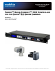


Quick-Connect CCU Controller for Canon BU Series Cameras
Quick-Connect CCU for Canon BU Series Cameras - Installation and User Guide 342-0152 Rev. A Page 5 of 8
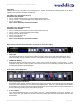
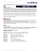
Rear Panel Controls and I/O (from left to right):
1. Power Supply Input:
12 VDC 1.0 Amp Power Supply Input on a 5.5mm OD x 2.5mm ID connector.
2. RS-232 IN on RJ-45:
RS-232 Input from ProductionVIEW or PTZ controller. Daisy Chain control is not supported.
3. RS-232 OUT on RJ-45:
RS-232 on RJ-45 provides for bi-directional control to the camera.
4. Tally on 2-pin Phoenix-type connector:
Contact closure illuminates the LED on front panel allowing indication of which CCU/camera combination is
active in a multi-camera/CCU installation.
5. Camera Settings Dip Switch:
The CCU Controller has an 8-position dip switch on the rear panel to allow for different modes of functionality
and future functionality. For the Canon BU Series cameras, Dip Switch #3 should be in the UP position
and all other switches should be in the down position.
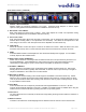
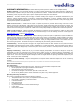
Basic System Connectivity Examples:
• BU-50/51 with Quick-Connect CCU Controller and ProductionVIEW HD-SDI Console
• BU-45/46 with Quick-Connect CCU Controller and ProductionVIEW Precision Camera Controller
RS-232 RS-422
RS-232
RS-232
RS-232
HD-SDI
Canon
BU-50/51
Canon
BU-45/46
HD-SDI
To Switcher
Adapters
Adapter
Quick-Connect CCU
Quick-Connect CCU
ProductionVIEW HD-SDI
ProductionVIEW Precision Camera Controller