
Owner manual


CeilingVIEW 70 PTZ – Document 010-2304-000 Rev. E
Page 2 of 14
Read and understand all instructions before using. Do not operate
the camera if the camera has been dropped or damaged. In this
case, a Vaddio technician must examine the product before
operating. To reduce the risk of electric shock, do not immerse in
water or other liquids and avoid extremely humid conditions.
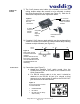
Carefully remove the device and all of the parts from the packaging.
Unpack and identify the following parts:
• One (1) CeilingVIEW 70 PTZ Camera Module
• One (1) Sony RM-EV100 IR Remote Controller
• One (1) White trim ring with IR sensor attached
• One (1) Vaddio Quick-Connect Box
• One (1) Vaddio PowerRite 15VDC Power Supply
• One (1) AC power cable for Power Supply
• One (1) 12’ (4.57m) S-Video cable
• Two (2) Adjustable ceiling tile support rails
• One (1) RJ-45 to DB9 EZCamera™ Control Adapter
• Mounting Hardware
• Installation and User Guide (010-2304-000 Rev. B)
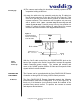
The CeilingVIEW 70 PTZ is an integrated document/object camera
specifically designed for installation in a suspended acoustic ceiling
tile above a table or work surface or in a position to be used as an
auxiliary PTZ camera. Recommended ceiling heights are between
8 and 12 feet.
• Be sure to check above the ceiling tile where you plan to install
the camera to make sure the area is clear and that there is
enough room for the CeilingVIEW Camera Module and all of its
components.
• Keep in mind that other than viewing straight down, the
CeilingVIEW PTZ has the capability of panning +/-170 degrees
from center.
• The camera may be used with any 2’ tile. The camera module
enclosure and the tile support rails allow for flexibility and
positioning freedom when used with 2'x2' and 2'x4' ceiling tiles.
• For cutting ease, remove the marked ceiling tile and place on a
suitable and safe work surface
UNPACKING
Use only the power supply provided with the CeilingVIEW 70 PTZ
camera system. Use of any unauthorized power supply will void any
and all warranties.
IMPORTANT
SAFEGAURDS
INSTALLATION
Before
Installing