
Owner's manual


CeilingVIEW HD HideAway Manual
CeilingVIEW HD HideAway Manual, Document Number 342-0289 Rev. B Page 5 of 24
STEP BY STEP INSTALLATION INSTRUCTIONS:
The CeilingVIEW HD HideAway is a motorized lift system enclosure specifically designed for Vaddio HD Cameras
to be installed in a suspended acoustic ceiling tile. Recommended average room ceiling height range is between
8’ and 12’ (2.44m to 3.66m). It can also be used in larger group rooms, lecture halls or auditoriums depending on
the system design requirements.
Before Starting the Installation:
Before starting the installation of the CeilingVIEW HD HideAway, check above the ceiling where you plan to
install the motorized camera lift system and make sure the area is clear of obstructions and confirm that there
is adequate room for the motorized camera lift system enclosure. Verify that you have proper building
structure to attach the required seismic bracing cable and support cables for the CeilingVIEW HD HideAway.
All above ceiling work must conform to local building codes and should be performed by qualified personnel.
The motorized camera lift system back box and ceiling tile brace allow for superior flexibility and positioning
freedom when used with 2’x 2’ and 2’x 4’ ceiling tiles. The motorized camera lift system does not have to be
mounted in the center of the tile. The motorized camera lift system back box can be turned to position the
camera in four directions in the ceiling tile brace as well (see Figure 10). (Please review all installation
instructions prior to starting installation).
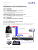
When terminating the Cat-5e cabling make sure that each cable is individually marked and tested at each end
for proper termination with a Cat-5e continuity tester.
Important Note: It is very important to set the IR Frequency in the CeilingVIEW HD HideAway to
match the IR Frequency of the Vaddio Camera in order to use the Vaddio IR Remote Commander.
The Vaddio IR Remote Commander can then be utilized to set the Upper and Lower Lift Stop
Settings in the CeilingVIEW HD HideAway and to provide PTZ Control/Power of the Vaddio HD
Camera.
STEP 1: Matching the IR Frequency of the CeilingVIEW HD HideAway and the Vaddio ClearVIEW HD
Camera:
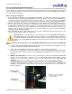
A. Remove the CeilingVIEW HD HideAway Motorized Back Box Assembly from the shipping carton and
position it vertically on a suitable and safe work surface.
B. Remove the nine (9) Phillips screws from the Front Access Panel and remove the panel.
Note: There is a safety interlock switch on the upper left side of the CeilingVIEW HD HideAway Back Box
Assembly that will not allow operation of the CeilingVIEW HD HideAway with the Front Access Panel
removed.
C. Matching the IR Frequency: There are three (3) IR frequency settings for all Vaddio ClearVIEW HD
Cameras. They are referred to as Camera 1, 2 or 3 on the Vaddio IR Remote Commander. The IR
settings are set by dip switch settings on both the Vaddio HD Camera and the CeilingVIEW HD
HideAway.
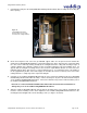
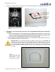
Setting the Dip Switches on the Main Printed Circuit Board in the CeilingVIEW HD HideAway:
The Main Printed Circuit Board (PCBA) is located on the left inside panel of the CeilingVIEW HD
HideAway. The Dip Switches are located on the lower side of the board and faces the Front Access
Panel (see Figure 3).
Dip Switches 1-6
(top to bottom)
Main Printed Circuit
Board (PCBA)
Figure 3: Location of dip switches
on the main printed circuit board
assembly (PCBA)